


37
OIL SYSTEM
A. Oil Charge
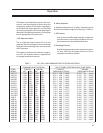
Charge the oil separator with the proper quantity of
lubricating oil (see Table 2 in the Installation Section).
CAUTION
It is imperative you charge the oil into the receiver/
separator prior to energizing the control panel to
prevent burning out the immersion heater in the
separator/receiver.
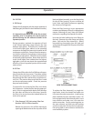
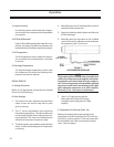
During operation, maintain the separator oil level
in the normal operating range between the two
bullseye sight glasses. If the oil level is visible only
in the lowest sight glass, add oil to the operating
compressor through the connection located at the
compressor suction inlet. Pump oil into the compres-
sor until the oil level in the separator is between the
two bullseye sight glasses. Watch this level carefully
to maintain proper operation. Never allow the oil to
reach a level higher than indicated on the highest
sight glass, since this may impair the operation and
efficiency of the oil separator portion of this combi-
nation vessel.
B. Oil Filter
Change the oil filter after the first 200 hours of opera-
tion, as noted on the hour meter. Thereafter, replace
the filter every six months, or when the oil pressure
drop through the filter reaches 45 psi, whichever oc-
curs first. The pressure drop across the filter is read
on the microprocessor panel. Check the pressure
drop and record it daily.
To prepare for the removal of the filter, shut down
the compressor. Isolate the filter housing appropri-
ately. If unit is equipped with duplex filter housings
the unit does not have to be shut down, however
the filter to be serviced must be isolated before the
tank can be opened.
1. Filter Removal, VSG Units using Vilter Part
Number1833Coillterelements.
Release the pressure in the oil filter housing by
opening the bleed valves at the stop valve in the
block and bleed assembly, or at the bleed valve
for the oil filter housing. Be sure to follow all
Local, State, and Federal ordinances regarding
the recovery of refrigerants.
Drain the filter housing in to an appropriate
container and dispose of the oil in a appropriate
manner following all Local, State and Federal
ordinances regarding the disposal of used oil.
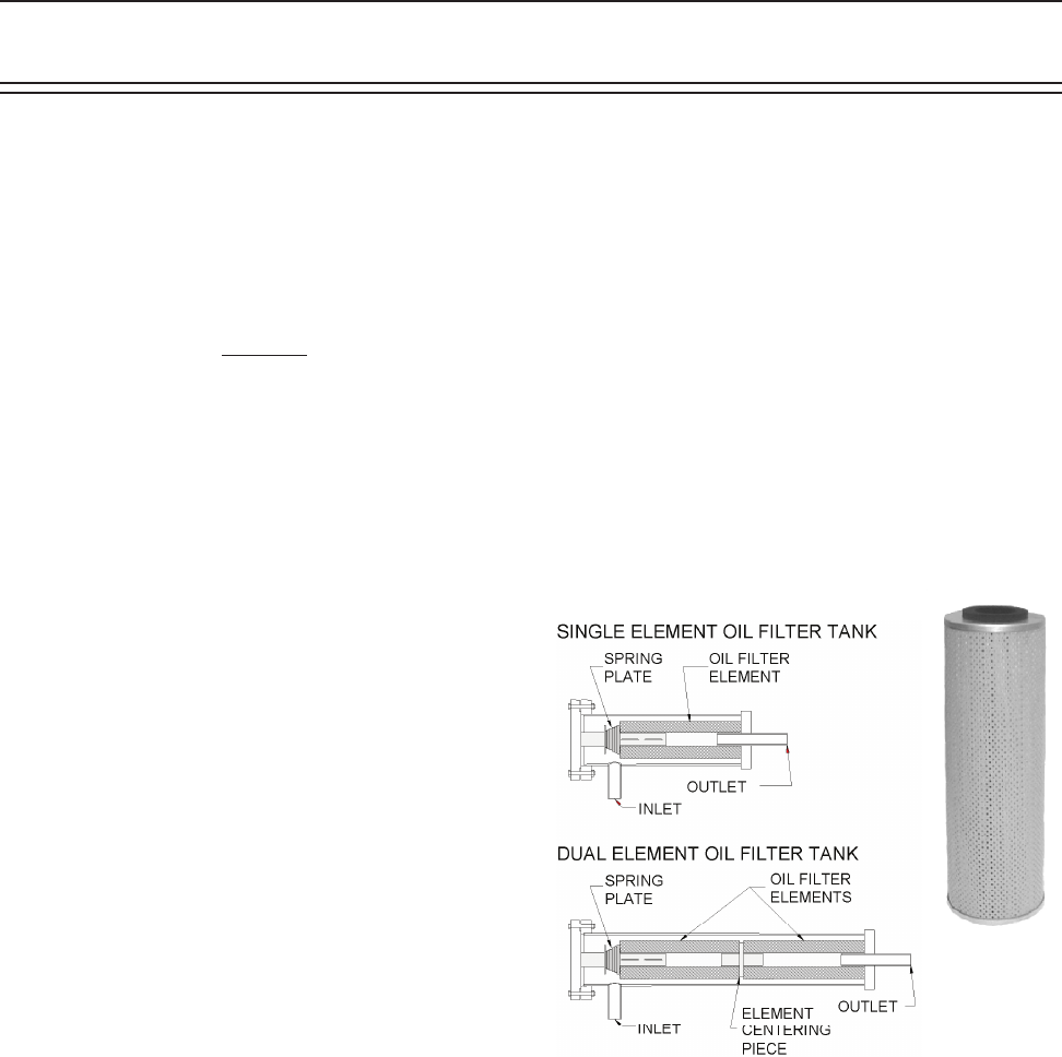
Unscrew the bolts holding the cover flange to
the tank. Remove the cover flange and spring
plate. Pull out the filter element(s). Before
reassembling, thoroughly clean the tank and
spring plate to lengthen the life span of the filter
element(s).
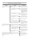
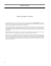
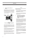
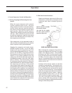
FIGURE 1.
1833C FILTER ELEMENT TANKS
To replace the filter element(s), on single ele-
ment tanks, insert the element and make sure
it fits onto the outlet connection. Install spring
plate, and bolt the cover assembly in place. On
units equipped with dual element tanks, insert
inner element and make sure it fits onto the
outlet connection. Put the centering piece on
the outer element and slide into tank making
sure the center piece fits into the inner element.
Put spring plate on outer element and bolt the
cover assembly in place.
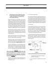
Operation
1833C
Filter
Element