


59
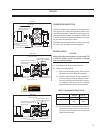
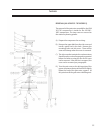
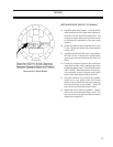
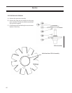
GaterotorforC-angeModels
INSTALLATION (All VSM 301-701 Models)
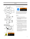
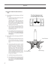
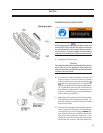
A) Install the gate rotor support. Carefully tilt the
roller bearing end of the gate rotor support to-
wards the suction end of the compressor. The
compressor input shaft may have to be rotated
to facilitate the installation of the gate rotor
support.
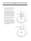
B) Install the roller bearing housing with a new
O-ring. Tighten the bolts to the recommended
torque value.
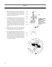
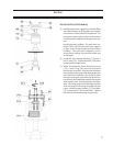
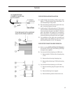
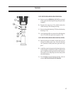
C) Install the spindle with shims and o-ring, tighten
the bolts to the recommended torque value,
measure the clearance between the shelf and
blade.
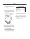
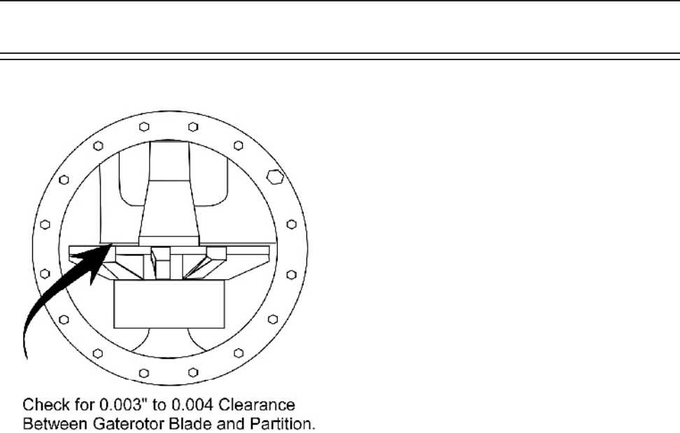
D) Check the clearance between the entire gate
rotor blade and the shelf, rotate the gate rotor
to nd the tightest spot. It should be between
0.003”-0.004”. Make adjustments, if necessary.
It is preferable to shim the gate rotor blade
looser rather than tighter against the shelf.
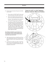
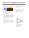
E) Once the clearance is set remove the spindle.
Install new o-ring, apply Loctite 242 thread
locker to the socket head cap screw clamping
the thrust bearings to the spindle. Torque all
bolts to the recommended torque values.
F) Install side covers with new gaskets. Tighten
bolts to the recommended torque value. The
unit can now be evacuated and leak checked as
outlined in section 0.03.
Service