


39
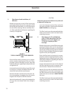
4. Filter Removal, VSS and VSM Units (after
5/1/00) when using Vilter Part Numbers
3109A (16” Duplex), or 3110A (39” Du
plex) oil filter housings.
Isolate the bowl to be worked on by turning
handle. The handle will cover the drain valve of
active element. Close commuter valve in center of
handle. Release the pressure in the isolated bowl
by bleeding through the stop valve on the oil filter
cover for Duplex (Vilter Part #3109A or 3110A),
or through the stop valve for the oil filter hous-
ing. Be sure to follow all Local, State and Federal
ordinances regarding the recovery of refrigerants.
Drain the filter bowl or housing in to an appro-
priate container and dispose of the oil in a ap-
propriate manner following all Local, State and
Federal ordinances regarding the disposal of used
refrigeration oil.
Loosen and remove the cover on the bowl of the
filter tank by turning it in a counter clockwise
direction. Remove the used element.
Wet the O-ring in the new element with clean
refrigeration oil. Insert the new element into the
filter tank with the close end visible and attach
the cover to the bowl. HAND TIGHTEN the cover.
The filter housing can be evacuated and then
slowly pressurized by opening the commuter
valve on handle. This will pressurize the housing.
Check for leaks. The filter can now be returned
to service. Repeat for other filter bowl if needed.
CAUTION
When changing filter, discard clogged filter only. Save
and reuse spring plate and centering piece. This filter
MUST be installed with the spring plate. A compressor
that is allowed to operate without the spring plate is
running with unfiltered oil.
The filter housing can be evacuated and then
slowly pressurized to check for leaks before re-
turning to service.
C. Oil Pressure Regulating
On units with a full time oil pump, the back pres-
sure regulator, in the oil supply line from the sepa-
rator, controls upstream pressure to the compres-
sor bearings and should be adjusted to hold the oil
pressure at 50 psig above suction pressure. Excess
oil not required for bearing lubrication is passed
through the regulator and flows into the separator.
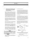
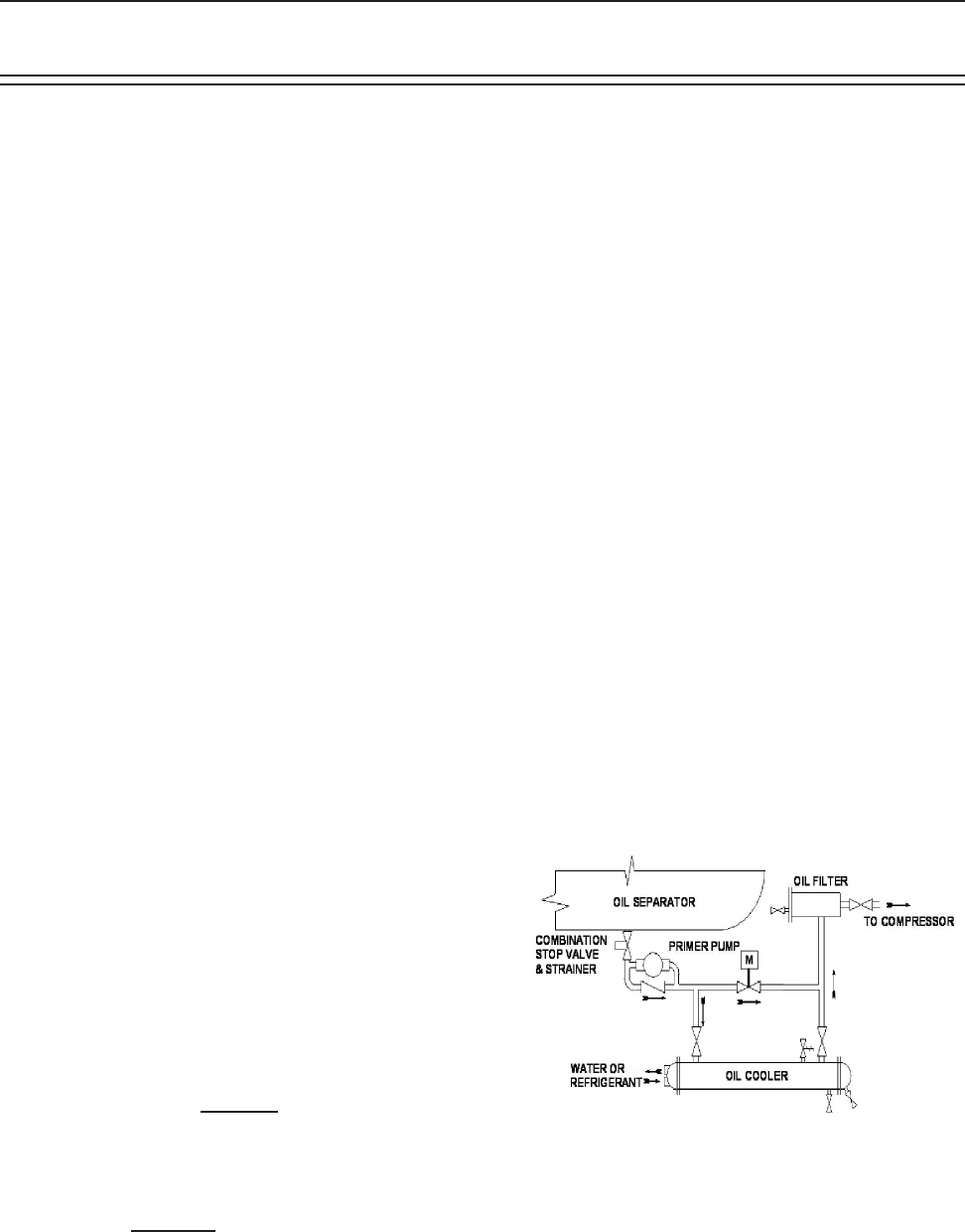
D. Oil Cooling
Various types of oil coolers can be used to main-
tain the oil injection temperature, usually either
a water-cooled shell-&-tube heat exchanger
mounted locally or a remotely located air-cooled
fan-coil unit. In either case, the oil temperature
control valve operates the same. (See Appendix
A: Pre Start Up for Remote Oil Coolers)
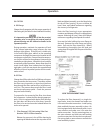
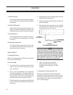
A two-way ball valve is located in the main oil line
between the oil separator and the compressor.
The oil cooler is piped in parallel to the oil tem-
perature control valve, which acts as a by-pass
valve (Figure 3).
FIGURE 3.
TYPICAL WATER COOLED OIL COOLER DIAGRAM
1. Temperature Control Valve Installation
& Position Indication
1.1 The ball valve is installed with the ball
closed.
Operation