


52
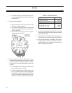
TABLE 2. GATE ROTOR FLOAT
E) Readings could be higher than 0.020. If readings
is greater than 0.030 over table tolerance contact
Vilter’s home ofce.
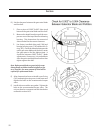
F) Inspect the main and gate rotors for signs of ab-
normal wear due to dirt or other contaminants.
G) After the inspection is complete, the covers,
coupling center member and guard can be rein-
stalled and the unit can then be evacuated and
leak checked before starting.
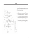
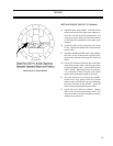
4) Add both readings, the total indicator move-
ment is the bearing oat and this should not
exceed 0.003”.
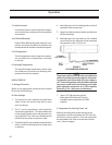
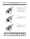
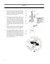
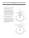
C) Gate rotor bearing oat.
1) Remove the side covers and position a dial
indicator on the gate rotor.
2) Use a lever arm pivoting on a bolt with a small
block of wood against the gate rotor blade to
protect the blade.
3) The maximum amount of bearing float
should not exceed 0.002”.
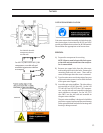
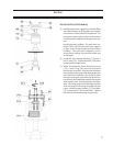
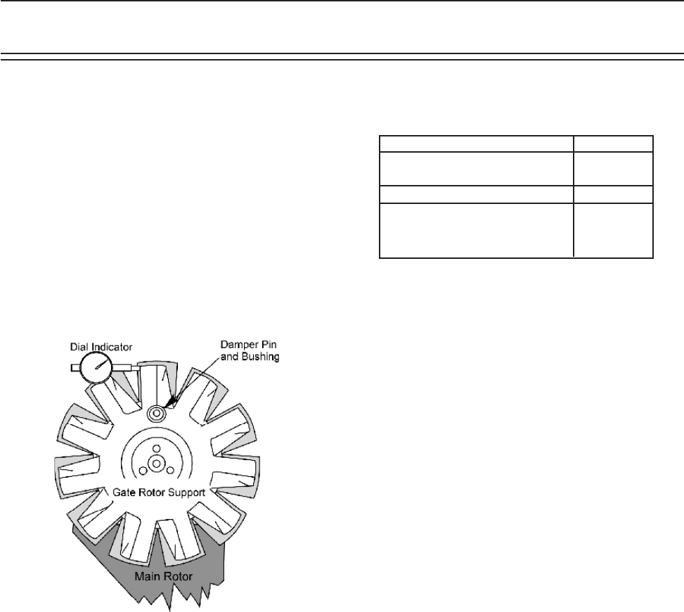
D) Measure the gate rotor to blade float. Some
movement between blade and support is neces-
sary to prevent damage to the compressor blade,
however at no time should the blade uncover the
support.
1) Position the blade with the gate rotor damper
pin and 90º to the main rotor.
2) Position a dial indicator at the tip of the sup-
port. The total movement of the damper pin
in the bushing is the gate rotor oat. Refer to
table 0.2 to nd the maximum blade to sup-
port oat (on new compressor parts only).
MODEL FLOAT
VSM 301 THRU 401 0.045”
VSM 501 THRU 701 0.045”
VSS 291 THRU VSS 601 0.045”
VSS 751 & VSS 901 0.055”
VSS 1051 & VSS 1201 0.060”
VSS 1551 & VSS 2101 0.060”
Service