


41
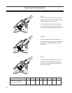
6.2 99% to 1% OPEN
oil flow stream is partially by-passing the oil
cooler and partially diverted to the oil cooler
6.3 0% OPEN
oil flow stream is entirely diverted to the oil
cooler
G. Control Settings
The oil temperature control setpoints are en-
tered on the compressor controller screen “Oil
Mixing Valve PID (Oil Return from Cooler)”.
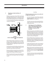
8.0 Rotating the Actuator for Convenience of
Installation
The actuator can be rotated to any one of four
positions.
8.1 Remove both 120V and 24V power from the
actuator.
8.2 Disconnect electrical leads at actuator.
8.3 Remove four cap screws that fasten the
actuator to the valve mounting bracket.
8.4 Lift the actuator off the valve stem.
8.5 Rotate the actuator to the desired position.
8.6 Slide actuator down on the valve stem.
8.7 Secure the actuator to the valve mounting
bracket with four cap screws.
8.8 Re-connect the electrical leads at the actua-
tor.
8.9. Restore 120V and 24V power to the actuator.
NOTE: The ball valve and the actuator must al-
ways be assembled in the CLOSED position. See
Section 3. Calibration above.
CAUTION: Be careful not to move the ball stem
during this operation. Turning the ball valve 90°
in either direction will reverse the control action
of the valve and the compressor will experience
high oil temperature within minutes. Turning
the ball valve 180° has no detrimental effect.
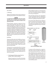
9. Manual Override
The actuator has a handwheel that can be en-
gaged to override the electrically determined
position of the ball valve.
Push and rotate to engage.
Push a second time to de-clutch.
CONTROL SYSTEM
Equipped for automatic operation, the screw com-
pressor unit has safety controls to protect it from
irregular operating conditions, an automatic start-
ing and stopping sequence, capacity and volume
ratio control systems.
Check all pressure controls with a remote pres-
sure source, to assure that all safety and operating
control limits operate at the point indicated on the
microprocessor.
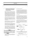
The unit is equipped with block and bleed valves
that are used to recalibrate the pressure transduc-
ers. To use the block and bleed valves to recalibrate
the pressure transducers, the block valve is shut
off at the unit and the pressure is allowed to bleed
off by opening the bleed valve near the pressure
transducer enclosure. The transducer can then be
calibrated at atmospheric pressure (0 psig), or an
external pressure source with an accurate gauge
may be attached at the bleed valve.
The discharge pressure transducer cannot be iso-
lated from its pressure source, so it is equipped with
only a valve to allow an accurate pressure gauge to
be attached and the pressure transducer calibrated
at unit pressure.
Recheck the transducers periodically for any drift
of calibration.
Operation