


61
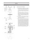
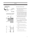
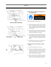
GATE ROTOR BLADE INSTALLATION
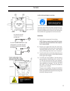
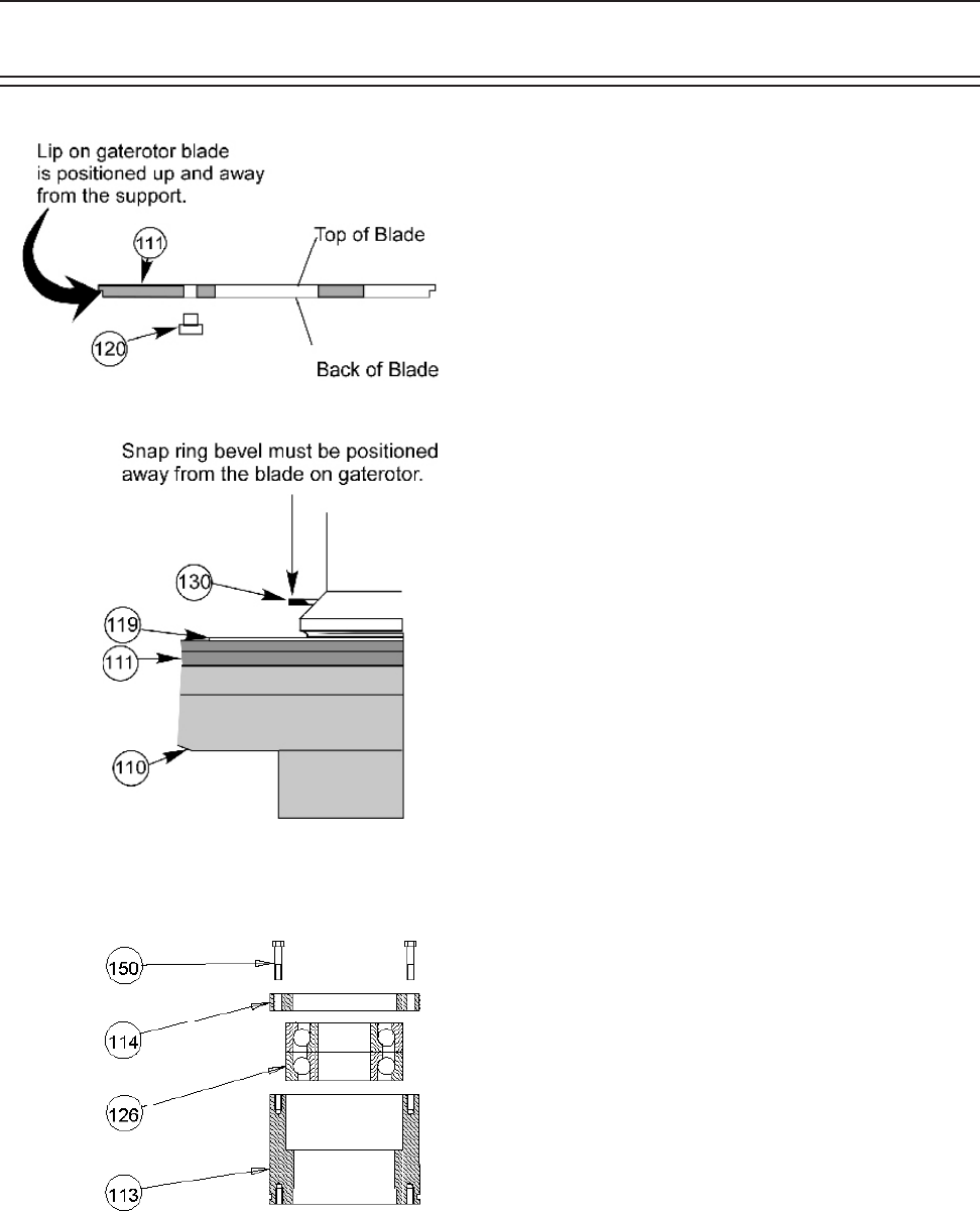
A) Install damper pin bushing (120) in gate rotor
blade (111) from the back side of the blade. Be
sure the bushing is fully seated.
B) Place the blade assembly on the gate rotor sup-
port. Locating Damper over pin.
C) Install washer (119) and snap ring (130) on gate
rotor assembly. The bevel on the snap ring must
face away from the gate rotor blade. After the
gate rotor blade and support are assembled,
there should be a small amount of rotational
movement between the gate rotor and support.
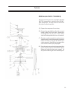
D) For installation of the gate rotor assembly and
setting of gate rotor clearance, refer to section
INSTALLATION (All VSG 301-701 Models).
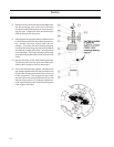
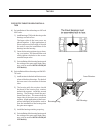
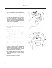
GATE ROTOR THRUST BEARING REMOVAL
A) Refer to section INSTALLATION (All VSS Models)
for removal of the gate rotor bearing housings
and gate rotor supports.
B) For removal of thrust bearings on VSM units:
1) Remove bolts (150) from the clamping ring
(114).
2) Remove thrust bearing clamping ring.
3) Remove thrust bearings (126) from housing
(113).
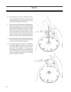
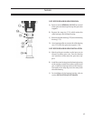
C) For removal of thrust bearings on VSS units:
1) Remove retaining ring from gate rotor sup-
port.
2) Remove bearings from support.
3) Remove bearing retainer from inner race.
Service
(with Relief)