


25
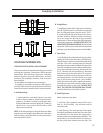
COUPLING INFORMATION
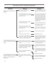
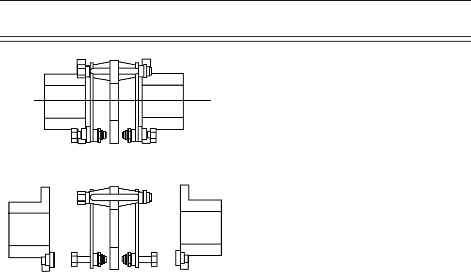
COUPLINGS INSTALLATION AND ALIGNMENT
These instructions are intended to help you to install
and align the coupling. Covered here will be general
information, hub mounting, alignment, assembly,
locknut torquing, discpack replacement, and part
numbers. The coupling as received, may or may not
be assembled.
*If assembled, the locknuts are not torqued.
*If coupling is assembled, remove the bolts that at-
tach the hubs to the disc packs. Remove both hubs.
Leave the disc packs attached to the center member.
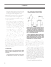
A. Hub Mounting:
1. Clean hub bores and shafts. Remove any nicks
or burrs. If bore is tapered, check for good contact
pattern. If the bore is straight, measure the bore
and shaft diameters to assure proper t. The key(s)
should have a snug side-to-side t with a small
clearance over the top.
NOTE: If the hub position on the shaft does not allow
enough room to install the short bolts in the hub after
hub mounting, install the bolts and disc pack before
mounting hub on shaft.
B. Straight Bore:
1. Install key(s) in the shaft. If the hub is an interfer-
ence t, heat the hub in an oil bath or oven until
bore is sufciently larger than the shaft. 350º F.
is usually sufcient. An open ame is not recom-
mended. However, if ame heating is necessary,
use a very large rose bud tip to give even heat
distribution. A thermal heat stick will help deter-
mine hub temperature. DO NOT SPOT HEAT THE
HUB OR DISTORTION MAY OCCUR. With the hubs
expanded, slide it up the shaft to the desired axial
position. A pre-set axial stop device can be helpful.
C. Taper Bore:
1. Put the hub on the shaft without key(s) in place.
Lightly tap hub up the shaft with a soft hammer.
This will assure a metal-to-metal t between shaft
and hub. This is the starting point for the axial
draw. Record this position between shaft and hub
face with a depth micrometer. Mount a dial indica-
tor to read axial hub movement. Set the indicator
to “0”. Remove hub and install key(s). Remount
hub, drawing it up the shaft to the “0” set point.
Continue to advance hub up the taper to the de-
sired axial position. Use the indicator as a guide
only. A pre-set axial stop device can be helpful.
Check the nal results with a depth micrometer.
The hub may have to be heated in order to reach
the desired position on the shaft. DO NOT SPOT
HEAT THE HUB OR DISTORTION MAY OCCUR.
Install shaft locknut to hold hub in place.
D. Shaft Alignment.
Move equipment into place.
1. Soft Foot. The equipment must sit at on its
base (+/- 0.002 inches). Any soft foot must be
corrected now.
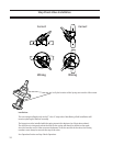
2. Axial Spacing. The axial spacing of the shafts
should be positioned so that the disc packs (ex-
ing elements) are flat when the equipment is
running under normal operating conditions. This
means there is a minimal amount of waviness in
the disc pack when viewed from the side. This
Coupling Installation