


3-8. INPUT RESISTANCE
This test verifies the input resistance of the oscilloscope module. A four-wire measurement is used for ac-
curacy at 50 Ω.
Specification:
1 M Ω ± 1% and 50 Ω ± 1%
Equipment Required:
The following equipment is required for the test. Procedures are based on the model or part numbers rec-
ommended.
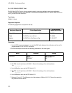
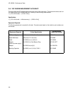
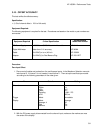
Equipment Required Critical Specification
Recommended
Model/Part Number
Digital Multimeter
Cables (2)
Adapter
Adapters (2)
Measure resistance (4-wire) better than 0.25%
accuracy
50 Ω BNC (m to m) 48-inch
50 Ω BNC Tee (m)(f)(f)
50 Ω BNC (f) to Dual Banana Plug
HP 3458A
HP 10503A
HP 1250-0781
HP 1251-2277
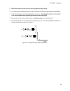
Procedure:
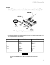
1. Set up the multimeter to make a 4-wire resistance measurement.
2. Use the BNC-to-banana adapters to connect one end of each BNC cable to the 4-wire resistance
connections on the multimeter, and connect the free ends of the cables to the BNC Tee.
3. Connect the male end of the BNC tee to the channel 1 input of the oscilloscope module. Set up the
oscilloscope module according to the following parameters in the order given:
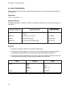
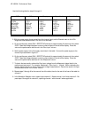
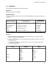
Menu Selection Setting
Channel
Trigger
Input
Probe
V/Div
Offset
Coupling
Mode
1
1:1
20 mV
0 V
50 Ω / DC
Immediate
HP 16532A - Performance Tests
3-4