


4. Select RUN - SINGLE. The clicking of attenuator relays should be audible. Verify resistance read-
ings on the digital multimeter of 50 Ω ± 0.5 Ω (49.5 to 50.5 Ω).
5. In the Channel menu change the Coupling field to 1 MΩ/DC.
6. Select RUN. The clicking of attenuator relays should be audible. Verify resistance readings on the
digital multimeter of 1 MΩ ± 10 kΩ (0.990 to 1.010 MΩ).
7. In the Channel menu change the Coupling field to 50 Ω/DC and V/Div to 200 mV/Div. Repeat steps
4 through 6.
8. In the Channel menu change the Coupling field to 50 Ω /DC and V/Div to 1 V/Div. Repeat steps 4
through 6.
9. In the Channel menu change the Coupling field to 50 Ω /DC and V/Div to 4 V/Div. Repeat steps 4
through 6.
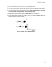
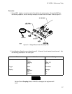
10. Connect the male end of the BNC tee to the channel 2 input of the oscilloscope module.
11. Repeat steps 3 through 9 for channel 2, replacing channel 1 with channel 2 where applicable.
Note
If a reading is not within limits, then the attenuator for the out-of-bounds channel
should be replaced. See "Service" in Section VI.
HP 16532A - Performance Tests
3-5