


5. If a trigger cable was determined to be faulty, replace the faulty trigger cable on the oscilloscope
module (refer to paragraph 6-10). Otherwise, skip to step 6.
6. If an attenuator was determined to be faulty, replace the faulty attenuator on the oscilloscope mod-
ule (refer to paragraph 6-11). Otherwise, skip to step 7.
7. If the oscilloscope module was determined to be faulty, remove the attenuators from the oscillo-
scope module (refer to paragraph 6-11).
8. Acquire a replacement oscilloscope module and install the attenuators on the replacement oscillo-
scope module (refer to paragraph 6-11).
9. Reinstall the repaired (or replacement) oscilloscope module in the mainframe (refer to the next pro-
cedure "Oscilloscope Module Replacement Procedure").
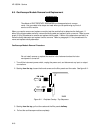
Oscilloscope Module Replacement Procedure
1. If you have not already done so, pull the installed boards half way out of the card slots (refer to
steps 1 through 3 of the preceding procedure "Oscilloscope Module Removal").
2. Determine which modules you want to install in the mainframe, and the slots where you want them
installed.
3. Starting with the bottom slot, slide each module to be installed approximately halfway into the main-
frame card slot.
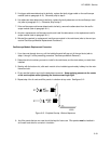
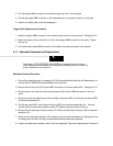
4. Firmly seat the bottom card into the backplane connector. Keep applying pressure to the center
of the card endplate while tightening the thumb screws finger tight.
5. Repeat step 4 for all cards and filler panels in a bottom-to-top order. See figure 6-12.
6. Any filler panels that are not used should be kept for future use. Filler panels must be installed in
all unused card slots for correct air circulation.
Figure 6-12. Endplate Overlap - Bottom Sequence
HP 16532A - Service
6-19