


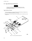

Attenuator Replacement Procedure:
a. Gently push the attenuator assembly (A2) straight down on the board assembly (A1) being careful
not to damage the connector and the components beneath the attenuator assembly. See figure
6-13.
b. Attach the attenuator assembly (A2) to the board assembly (A1) with the two attenuator retainer
screws (H7).
c. Assemble the rear panel (MP1) and the ground spring (MP2) to the board assembly (A1) and attach
them with the three end plate screws (H6). You may need to loosen the attenuator retainer screws
(H7) before assembling the ground spring to the board assembly, then tighten the attenuator
screws (H7) when the assembly is finished.
d. Attach the SMB connectors to the rear panel (MP1) with two hex nuts (H4) and two washers (H5).
e. Attach the BNC connectors to the rear panel (MP1) with four hex nuts (H3).
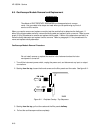
Note
Tighten the hex nuts down so that they will not interfere with the installation of the
board above the oscilloscope module. One of the flat surfaces on the outside
edge of the nut should be parallel with the top edge of the rear panel.
HP 16532A - Service
6-22