


3-11. BANDWIDTH
This test checks the bandwidth of the oscilloscope module.
Specification:
Bandwidth (dc coupled) dc to 250 MHz
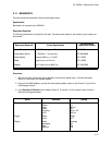
Equipment Required:
The following equipment is required for this test. Procedures are based on the model or part number rec-
ommended.
Equipment Required Critical Specification
Recommended
Model/Part Number
Signal Generator
Power Meter/Sensor
Power Splitter
Cable
Adapter
1 - 250 MHz at approx 170 mVrms
1 - 250 MHz ± 3% accuracy
Outputs differ by < 0.15 dB
Type N (m to m) 24-inch
50 Ω Type N (m) to BNC (m)
HP 8656B
HP 436/8482A
HP 11667B
HP 11500B
HP 1250-0082
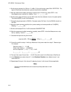
Procedure:
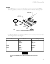
1. With the N cable, connect the signal generator to the power splitter input. Connect the power
sensor to one output of the power splitter.
2. Using an N-to-BNC adapter, connect the other power splitter output to the Channel 1 input of the
oscilloscope module.
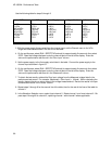
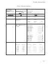
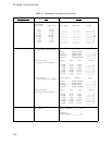
3. In the Waveform Selection menu delete channel 2. If channel 1 is not inserted, insert channel 1.
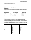
Set the following parameters.
Menu Selection Setting
Channel
Trigger
Display
Input
Probe
v/Div
Offset
Coupling
s/Div
Mode
Level
Mode
Average #
Grid
Markers
1
1:1
80 mV
0 V
50 Ω / DC
200 ns
Edge
0 V
Average
32
On
Off
HP 16532A - Performance Tests
3-11