


SECTION VI
Service
6-1. Introduction
The service policy for this instrument is replace-
ment of defective assemblies. This service manual
contains information for finding a defective
assembly. This section contains information for
servicing the HP 16532A Oscilloscope Module.
Included are a block level theory and procedures
for self diagnostics and troubleshooting. If the
module or a cable is determined faulty, procedures
are provided for module and cable replacement.
6-2. Safety Requirements
Specific warnings, cautions, and instructions are
placed wherever applicable throughout the
manual. These must be observed during all
phases of operation, service, and repair of the
module. Failure to comply with them violates
safety standards of design, manufacture, and
intended use of this module. Hewlett-Packard
assumes no liability for the failure of the customer
to comply with these safety requirements.
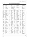
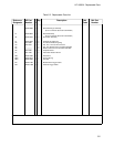
6-3. Recommended Test Equipment
Table 1-3 lists recommended test equipment. Any
equipment that satisfies the critical specification
given in the table may be substituted for the
recommended models.
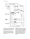
6-4. Module Block Diagram and The-
ory of Operation
The following paragraphs contain block level
theory of operation. This theory is not intended for
component level troubleshooting, rather it is to be
used to help isolate a module failure to card level.
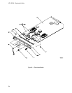
The HP 16532A Oscilloscope Module is contained
on one board. It runs at a 1 GSa/s digitizing rate,
with a 250 MHz single-shot (real-time) bandwidth,
8000 samples per measurement per channel, with
2-channel simultaneous acquisition which is
expandable to up to 8 channels. See figure 6-1.
6-5. Attenuator Theory of Operation
The channel signals are conditioned by the
attenuator/preamps, thick film hybrids containing
passive attenuators, impedance converters, and a
programmable amplifier. The channel sensitivity
defaults to the standard 1-2-4 sequence (other
sensitivities can be set also). However, the
firmware uses passive attenuation of 1, 5, 25, and
125, with the programmable preamp, to cover the
entire sensitivity range.
The input has a selectable 1 MΩ input impedance
with ac or dc coupling or a 50Ω input impedance
with dc coupling. Compensation for the passive
attenuators is laser trimmed and is not adjustable.
After the passive attenuators, the signal is split into
high-frequency and low-frequency components.
Low frequency components are amplified on the
main assembly, where they are combined with the
offset voltage. The ac coupling is implemented in
the low frequency amplifier.
The high- and low-frequency components of the
signal are recombined and applied to the input
FET of the preamp. The FET provides a high input
impedance for the preamp. The programmable
preamp adjusts the gain to suit the required
sensitivity and provides the output signal to the
main assembly. The output signal is then sent to
both the trigger circuitry and ADC.
6-6. Main Assembly Theory of
Operation
Acquisition
The acquisition circuitry provides the sampling,
digitizing, and storing of the signals from the
channel attenuators. The channels are identical.
The external trigger (ECL) input cannot be
displayed. Trigger signals from each channel and
the external triggers synchronize acquisition
through the time base circuitry. A 100 MHz
oscillator and a time base provide system timing
and sample clocking. A voltage-controlled
oscillator (VCO), frequency divider, and digital
HP 16532A - Service
6-1