


3. Pull the straight SMB connector on the cable through the hole in the rear panel.
4. Pull the right-angle SMB connector on the cable away from its mating connector on the board.
5. Install a new cable (refer to the next paragraph).
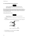
Trigger Cable Replacement Procedure:
1. Install the straight SMB connector on the cable through the hole in the rear panel. See figure 6-13.
2. Attach the washer (H5) and the hex nut (H4) to the straight SMB connector on the cable. Tighten
the hex nut.
3. Connect the right-angle SMB connector on the cable to its mating connector on the board.
6-11. Attenuator Removal and Replacement
The effects of ELECTROSTATIC DISCHARGE can damage electronic compo-
nents. Use grounded wriststraps and mats when performing any kind of service
to this instrument or the cards in it.
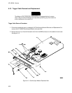
Attenuator Removal Procedure:
1. Follow the procedures given in paragraph 6-9 "Oscilloscope Module Removal and Replacement" to
remove the HP 16532A Oscilloscope Module to be serviced.
2. Remove the four hex nuts (H3) from the BNC connectors on the rear panel (MP1). See figure 6-13.
3. Remove the two hex nuts (H4) and the two washers (H5) from the SMB connectors on the rear
panel.
4. Remove the three end plate screws (H6) holding the rear panel (MP1) and the ground spring (MP2)
to the board assembly (A1).
5. Pull the rear panel (MP1) and the ground spring (MP2) from the board assembly (A1). You may
need to loosen the attenuator retainer screws (H7) before removing the ground spring.
6. Remove the two attenuator retainer screws (H7) holding the attenuator assembly (A2) to the board
assembly (A1).
7. Gently pull the attenuator assembly (A2) straight up from the board assembly (A1) being careful not
to damage the connector and the components beneath the attenuator assembly.
8. Install a new attenuator assembly (refer to the next paragraph "Attenuator Replacement Procedure").