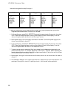
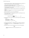
3. Set the signal generator for a 50 MHz and 35 mV rms signal. On the oscilloscope module select
RUN - REPETITIVE.
4. In the Auto-Measure menu read V
p_p
. Adjust the signal generator output level so that the signal is
close to and not more than 100 mV
p_p
.
5. In the Trigger menu adjust the trigger level for a stable display. The test passes if the trigger is sta-
ble. Record whether the trigger is stable or is not stable.
6. On the oscilloscope module select STOP. Set the signal generator frequency to 250 MHz and
70 mV rms signal level.
7. In the Channel menu change s/Div to 5 ns/Div and select RUN.
8. In the Auto-Measure menu read V
p_p
. Adjust the signal generator output level so that the signal is
close to and not more than 200 mV
p_p
.
9. In the Trigger menu adjust the trigger level for a stable display. The test passes if the trigger is sta-
ble. Record whether the trigger is stable or is not stable in the performance test record.
10. On the oscilloscope module select STOP. In the Channel menu select channel 2. In the Trigger
menu select Source channel 2. In the Waveform Selection menu delete channel 1 and insert
channel 2.
11. Repeat steps 1 through 9 for channel 2, replacing channel 1 with channel 2 where applicable.
Note
Failure of the trigger sensitivity test can be caused by a defective main
assembly.
HP 16532A - Performance Tests
3-16


