


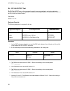
3. Select RUN - REPETITIVE. Wait approximately 15 seconds (averaging complete), then select
STOP. The display should read 0.00 V ± 320.0 mV as read from the markers voltage field. Record
the reading in the performance test record.
4. In the Channel menu, change the vertical sensitivity to 1 V/Div. Select RUN - REPETITIVE and wait
approximately 15 seconds (averaging complete), then select STOP. The display should read 0.00 V
± 80.0 mV. Record the reading in the performance test record.
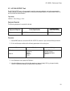
5. In the Channel menu, change the vertical sensitivity to 100 mV/Div. Select RUN - REPETITIVE and
wait approximately 15 seconds (averaging complete), then select STOP. The display should read
0.00 V ± 8.0 mV. Record the reading in the performance test record.
6. In the Channel menu, change the vertical sensitivity to 10 mV/Div. Select RUN - REPETITIVE and
wait approximately 15 seconds (averaging complete), then select STOP. The display should read
0.00 V ± 800.0 µV. Record the reading in the performance test record.
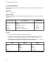
DC Input Offset
Set the Channel
Coupling
field to 1M
Ω
/ DC or damage to the equipment will
result.
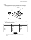
7. Use the BNC-to-banana adapter to connect the BNC cable between the power supply and channel
1 input. Monitor the power supply using a voltmeter.
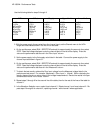
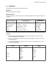
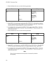
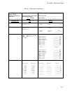
8. Use the following table for the next steps:
V/Div Offset Supply Min Max
1 V/Div
100 mV/Div
20 mV/Div
20 mV/Div
100 mV/Div
1 V/Div
− 35.00 V
− 10.00 V
− 2.00 V
+ 2.00 V
+ 10.00 V
+ 35.00 V
− 35.00 V
− 10.00 V
− 2.00 V
+ 2.00 V
+ 10.00 V
+ 35.00 V
− 35.4 V
− 10.1 V
− 2.02 V
+ 1.98 V
+ 9.90 V
+ 34.6 V
− 34.6 V
− 9.90 V
− 1.98 V
+ 2.02 V
+ 10.1 V
+ 35.4 V
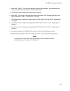
9. In the Channel menu set the V/Div range and offset per the first line of the table. Set the power
supply per the first line of the table.
10. On the oscilloscope, select RUN - REPETITIVE and wait approximately 15 seconds (averaging
complete), then STOP.
11. Read the voltage from the markers voltage field. It should be within the limits given in the table. Re-
cord the reading in the performance test record.
12. Repeat steps 7 through 10 for the remaining lines of the table using the V/Div range, offset, and sup-
ply voltages given in the table.
13. In the Channel menu select channel 2. In the Waveform Selection menu delete channel 1 and insert
channel 2.
14. Repeat steps 1 through 12 for channel 2, replacing channel 1 with channel 2 where applicable.
HP 16532A - Performance Tests
3-10