


TROUBLESHOOTING & REPAIR
F-62 F-62
POWER WAVE 355
Return to Section TOC Return to Section TOC Return to Section TOC Return to Section TOC
Return to Master TOC Return to Master TOC Return to Master TOC Return to Master TOC
PROCEDURE
1. Remove input power to the POWER WAVE
355/405.
2. Using a 5/16” nut driver remove the case wrap-
around cover.
3. Perform the Input Filter Capacitor Discharge
Procedure detailed earlier in this section.
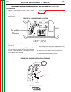
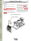
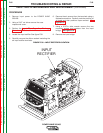
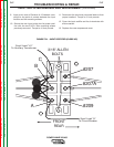
4. Locate the DC Bus Board. See Figure F.27.
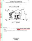
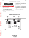
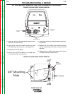
5. Using a 5/16” nut driver remove the two screws
from the bottom of the front of the machine. See
Figure F.28.
6. Using a phillips head screwdriver remove the two
screws and their washers from above and below
the input power switch. See Figure F.28.
7. Using a phillips head screwdriver remove the four
screws mounting the two welder output terminals
on the front of the machine. See Figure F.28.
8. The front of the machine may now gently be pulled
forward to gain access to the DC Bus Board.
Note: The front of the machine cannot be removed
completely, only pulled forward a few inches.
DC BUS BOARD REMOVAL AND REPLACEMENT (Continued)
DC BUS BOARD
W
A
R
N
IN
G
R
E
M
O
T
E
P
O
W
E
R
O
F
F
O
N
STATUS
THERMAL
LINCOLN
ELECTRIC
FIGURE F.27 DC BUS BOARD LOCATION