


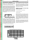


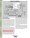
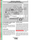
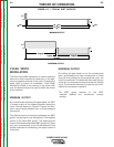

FIGURE E.2 – INPUT VOLTAGE AND PRECHARGE
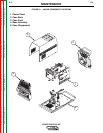
Control Board
Choke
Positive
Output
Terminal
Negative
Output
Terminal
Board
Current
Feedback
Reconnect
Switch
Output Voltage Sense
Input switch
Input
Rectifier
Auxiliary
Transformer
Fan
Power
Board
220
Receptacle
RS232 Supply +5VDC
Machine Control Supply
+15VDC, -15VDC, +5VDC
40VDC
42VAC
220 VAC
Main
Switch
Board
115VAC Fan Supply
Fan Control
V/F Capacitor Feedback (2)
Soft Start Control
Input Relay Control
Primary Current Feedback(2)
IGBT Drive Signal
Primary
Current
Sensor
Primary
Current
Sensor
{
P
o
w
e
r
W
a
v
e
4
0
5
o
n
l
y
65VAC
DC
Bus
Board
Wire
Feeder
Recp.
40VDC
Can Supply +5VDC
Arc
Link
Electrode
Sense
21 Lead
Voltage
Sense
Recp.
R232
Connector
Yellow
Thermal
LED
Status
Red/Green
LED
Thermostats
2
GENERAL DESCRIPTION
The Power Wave semi-automatic power source is
designed to be a part of a modular, multi-process
welding system. Depending on configuration, it can
support constant current, constant voltage, and pulse
welding modes.
The Power Wave power source is designed to be used
with the semi-automatic family of power feed wire
feeders, operating as a system. Each component in
the system has special circuitry to “talk with” the other
system components, so each component (power
source, wire feeder, user interface) knows what the
other is doing at all times. These components com-
municate with Linc-Net (a digital communications sys-
tem).
The POWER WAVE 355/405 is a high performance,
digitally controlled inverter welding power source
capable of complex, high speed waveform control.
Properly equipped, it can support the GMAW, GMAW-
P, FCAW, SMAW, GTAW, and CAC-A processes. It car-
ries an output rating of 350 Amps, 34 Volts at 60%
duty cycle and 300 Amps, 32 volts at 100% duty cycle.
INPUT LINE VOLTAGE, AUXILIARY
TRANSFORMER, & PRECHARGE
The POWER WAVE 355/405 can be connected for a
variety of three-phase or single-phase input voltages.
The initial power is applied to the 355/405 through a
line switch located on the front of the machine. Two
phases of the input voltage are applied to the auxiliary
transformer. The auxiliary transformer develops three
different secondary voltages. The 115VAC is applied,
via the main switch board, to the fan motor. The
42VAC is rectified and filtered. The 65VDC produced
by the Bus board rectifier is used by the Bus board to
provide 40VDC to the power board. 40VDC is also
applied to the wire feeder receptacle. PW405 models
have an additional 220VAC winding that is connected
to a 220 AC receptacle.
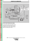
The input voltage is rectified by the input rectifier and
the resultant DC voltage is applied to the switch board
through the reconnect switch assembly located at the
rear of the machine. The reconnect switch connect the
two pairs of input capacitors either in a parallel (lower
voltage) or series (higher voltage) configuration to
accommodate the applied input voltage.
During the precharge time the DC input voltage is
applied to the input capacitors through a current limit-
ing circuit. The input capacitors are charged slowly
and current limited. A voltage to frequency converter
circuit located on the switch board monitors the
capacitor voltages. This signal is coupled to the con-
trol board. When the input capacitors have charged
to an acceptable level, the control board energizes the
input relays, that are located on the switch board,
making all of the input power, without current limiting,
available to the input capacitors. If the capacitors
become under or over voltage the control board will
de-energize the input relays and the 355/405 output
will be disabled. Other possible faults may also cause
the input relays to drop out.
THEORY OF OPERATION
E-2 E-2
POWER WAVE 355/405
Return to Section TOC Return to Section TOC Return to Section TOC Return to Section TOC
Return to Master TOC Return to Master TOC Return to Master TOC Return to Master TOC