


OPERATION
B-4 B-4
POWER WAVE 355/405
Return to Section TOC Return to Section TOC Return to Section TOC Return to Section TOC
Return to Master TOC Return to Master TOC Return to Master TOC Return to Master TOC
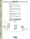
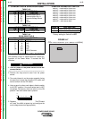
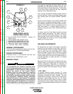
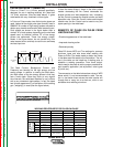
FIGURE B.1
10
4
6
1
3
2
5
7
8
9
CASE FRONT LAYOUT
POWER WAVE 355/405
5.
Internal POWER CIRCUIT BREAKER:
Protects 115
volt AC circuit.
6. LEAD CONNECTOR (SENSE LEAD)
7. DIAGNOSTIC CONNECTOR (RS-232)
8. WIRE FEEDER RECEPTACLE (5-PIN)
9. NEGATIVE TWIST- MATE TERMINAL
10. POSITIVE TWIST- MATE TERMINAL
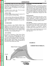
NOMINAL PROCEDURES
The Power Wave is designed to operate with 3/4" elec-
trode stick-out for CV and Pulse processes.
FRINGE PROCEDURES
Excessively short or long electrode stick-outs may
function only on a limited basis, if at all.
MAKING A WELD
The serviceability of a product or structure utiliz-
ing the welding programs is and must be the sole
responsibility of the builder/user. Many variables
beyond the control of The Lincoln Electric
Company affect the results obtained in applying
these programs. These variables include, but are
not limited to, welding procedure, plate chemistry
and temperature, weldment design, fabrication
methods and service requirements. The available
range of a welding program may not be suitable for
all applications, and the build/user is and must be
solely responsible for welding program selection.
------------------------------------------------------------------------
WARNING
The steps for operating the Power Wave will vary
depending upon the options installed in the user inter-
face (control box) of the welding system. The flexibility
of the Power Wave system lets the user customize
operation for the best performance.
First, consider the desired welding process and the
part to be welded. Choose an electrode material, diam-
eter, shielding gas and process (GMAW, GMAW-P,
etc.)
Second, find the program in the welding software that
best matches the desired welding process. The stan-
dard software shipped with the Power Waves encom-
passes a wide range of common processes and will
meet most needs. If a special welding program is
desired, contact the local Lincoln Electric sales repre-
sentative.
To make a weld, the Power Wave needs to know the
desired welding parameters. The Power Feed (PF)
family of feeders communicate settings to the Power
Wave through control cable connection. Arc length,
wire feed speed, arc control, etc. are all communicated
digitally via the control cable.
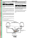
WELDING ADJUSTMENTS
All adjustments are made on the system component
known as the User Interface (Control Box), which con-
tains the switches, knobs, and digital displays neces-
sary to control both the Power Wave and a Power
Feed wire feeder. Typically, the Control Box is supplied
as part of the wire feeder. It can be mounted directly on
the wire feeder itself, the front of the power source, or
mounted separately, as might be done in a welding
boom installation.
Because the Control Box can be configured with many
different options, your system may not have all of the
following adjustments. Regardless of availability, all
controls are described below. For further information,
consult the Power Feed wire feeder instruction manu-
al.
• WFS / AMPS:
In synergic welding modes (synergic CV, pulse
GMAW) WFS (wire feed speed) is the dominant control
parameter, controlling all other variables. The user
adjusts WFS according to factors such as weld size,
penetration requirements, heat input, etc. The Power
Wave then uses the WFS setting to adjust its output
characteristics (output voltage, output current) accord-
ing to pre-programmed settings contained in the Power
Wave.