


Return to Section TOC Return to Section TOC Return to Section TOC Return to Section TOC
Return to Master TOC Return to Master TOC Return to Master TOC Return to Master TOC
POWER WAVE 355/405
TROUBLESHOOTING & REPAIR
F-6 F-6
Observe Safety Guidelines
TROUBLESHOOTING GUIDE
detailed in the beginning of this manual.
CAUTION
If for any reason you do not understand the test procedures or are unable to perform the test/repairs safely, con-
tact the Lincoln Electric Service Department for electrical troubleshooting assistance before you proceed. Call
1-800-833-9353(WELD).
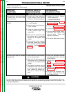
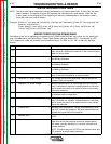
PROBLEMS
(SYMPTOMS)
POSSIBLE AREAS OF
MISADJUSTMENT(S)
RECOMMENDED
COURSE OF ACTION
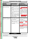
FUNCTION PROBLEMS
The machine regularly overheats
and the yellow thermal light is ON
indicating a thermal overload.
1. The welding application may
be exceeding the recommended
duty cycle of the POWER WAVE
355/405.
2. Dirt and dust may have clogged
the cooling channels inside the
machine.
3. Air intake and exhaust louvers
may be blocked due to inade-
quate clearance around the
machine.
4. Make certain the fan as needed
(F.A.N.) is operating properly.
The fan should operate when
welding voltage is present
and/or when there is an over
temperature condition.
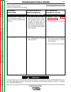
1. The 115VAC fan motor is con-
trolled by the control board via
the main switch board. Perform
the Fan Motor And Control
Test.
1. A thermostat or associated cir-
cuitry may be faulty. See the
wiring diagram. One normally
closed thermostat is located on
the output choke, one on the DC
Bus Board and the other is
located on the main switch
board heat sink. See the wiring
diagram.
Note: The Main Switch Board
Removal Procedure will be
required to gain access to
the heat sink thermostat.
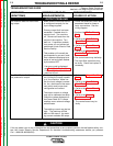
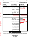
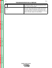
An attached wire feeder will not
function correctly. Apparently the
wire feeder is not being powered-
up.
1. Make certain the wire feeder
control cable is connected to
the wire feeder receptacle. See
the Wiring Diagram.
2. Check the two circuit breakers
located at the front of the
machine. Reset if tripped.
3. The wire feeder or control cable
may be faulty.
1. Check for 40 VDC on pin “D” (+)
and pin “E” (-) at the Power Wave
wire feeder receptacle. See
Wiring Diagram.
If 40 volts DC is Not present at
the Power Wave wire feeder
receptacle, perform the DC Bus
Board Test.
2. Check the DC Bus Board rectifi-
er. See Wiring Diagram.
3. Perform the T1 Auxiliary trans-
former Test.
4. If the 40 volts DC is present at
the Power Wave wire feeder
receptacle, the problem is in the
control cable or the wire
drive/control box.