


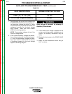


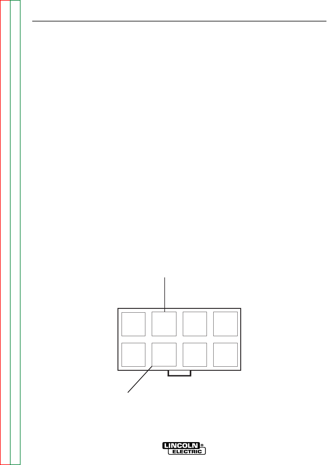
Plug J20
Lead 715+
1
2
3
4
7
8
65
Lead 716-
TROUBLESHOOTING AND REPAIR
FAN CONTROL AND MOTOR TEST (continued)
F-45 F-45
POWER WAVE 355/405
Return to Section TOC Return to Section TOC Return to Section TOC Return to Section TOC
Return to Master TOC Return to Master TOC Return to Master TOC Return to Master TOC
7. If the 115VAC is low or not present check cir-
cuit breaker CB2 located on the front panel. If
the circuit breaker is OK, perform The
Auxiliary Transformer Test. Check plug J22,
circuit breaker CB2 and associated leads for
loose or faulty connections. See the Wiring
Diagram.
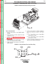
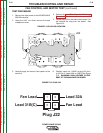
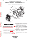
8. Energize the weld output terminals with the
PW 355/405 in mode 200. This mode can be
accessed using a wire feeder placed in mode
200 or a laptop computer and the appropriate
software. Carefully check for 115VAC at plug
J22 pin-1 to J22 pin-4 (fan leads). See Figure
F. 15. If the 115VAC is present and the fan is
not running then the fan motor may be faulty.
Also check the associated leads between plug
J22 and the fan motor for loose or faulty con-
nections. See the Wiring Diagram. WARN-
ING: HIGH VOLTAGE IS PRESENT AT THE
SWITCH BOARD.
9. If the 115VAC is NOT present in the previous
step then proceed to the fan control test.
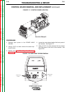
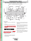
FAN CONTROL TEST PROCEDURE
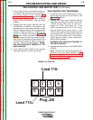
1. Locate plug J20 on the switch board. Do not
remove the plug from the switch board. See
Figure F.14 and F.16.
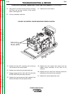
2. Energize the weld output terminals (Select
Weld Terminals ON) and carefully check for
+15VDC at plug J20 pin-6+ to J20 pin-2-
(leads 715 to 716). See Figure F.16. If the
15VDC is present and the fan is not running
then the switch board may be faulty. If the
15VDC is not present when the weld terminals
are energized then the control board may be
faulty. Also check plugs J20, J7, and all asso-
ciated leads for loose or faulty connections.
See the Wiring Diagram.
WARNING: HIGH VOLTAGE IS PRESENT AT
THE SWITCH BOARD.
3. Remove the input power to the POWER WAVE
355/405.
Note: The fan motor may be accessed by the
removal of the rear panel detailed in The
Current Transducer Removal and
Replacement Procedure.
4. Replace the case wrap-around cover.
FIGURE F.16 PLUG J20