


TEST PROCEDURE
1. Remove input power to the POWER
WAVE 355/405 machine.
2. Using a 5/16” nut driver, remove the case
wraparound cover.
3. Perform the Capacitor Discharge
Procedure detailed earlier in this section.
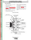
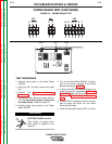
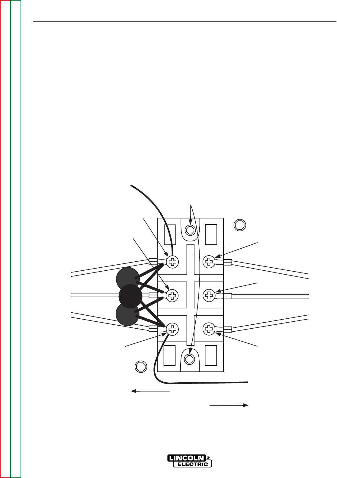
4. Locate the input rectifier and associated
leads. See Figure F.3.
5. Carefully remove the silicone sealant
from leads 207, 207A, and 209.
6. Using a phillips head screwdriver,
remove leads 207, 207A, and 209 from
the input rectifier.
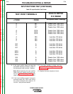
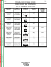
7. Use the analog ohmmeter to perform the
tests detailed in Table F.2. See the
Wiring Diagram.
8. Visually inspect the three MOV’S for
damage (TP1,TP2,TP3). Replace if nec-
essary.
TROUBLESHOOTING & REPAIR
F-20 F-20
POWER WAVE 355/405
Return to Section TOC Return to Section TOC Return to Section TOC Return to Section TOC
Return to Master TOC Return to Master TOC Return to Master TOC Return to Master TOC
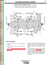
INPUT RECTIFIER TEST (CONTINUED)
#207A
#207
#209A
B
C
3/16" ALLEN
BOLTS
FRONT
REAR
Small Lead "A"
To Circuit Breaker
Small Lead "H1"
To Auxiliary Transformer
Figure F.3 Input Rectifier