


POWER WAVE 355/405
Return to Section TOC Return to Section TOC Return to Section TOC Return to Section TOC
Return to Master TOC Return to Master TOC Return to Master TOC Return to Master TOC
TROUBLESHOOTING & REPAIR
F-10 F-10
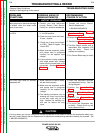
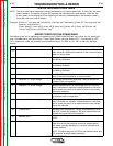
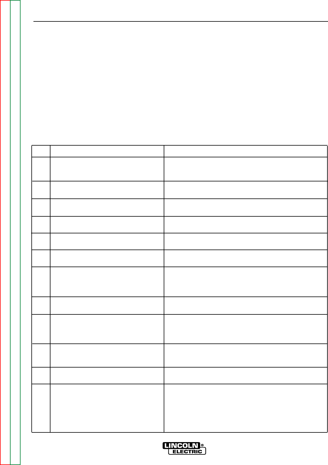
STATUS LED ERROR CODE TABLE
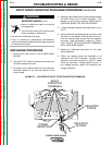
NOTE: The error code signal sequence is always preceded by a 2 second green light. If more than one error
code is present, a 4 second off signal will separate the individual error code signals. Note that the
[2 sec. green] is only displayed at the beginning of the entire code sequence, not between codes if
more than one error code is present.
Example: (Code. #11 “one long red” followed by “one short red”) followed by (Code. #21 “two long reds” fol-
lowed by “one short red”).
[2 sec. green] [1.2 sec. red] [1.6 sec. off] [0.4 sec. red] [4.0 sec. off] [1.2 sec. red] [0.4 sec. off]
[1.2 sec. red] [1.6 sec. off] [0.4 sec. red]
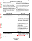
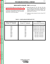
ERROR CODES FOR THE POWER WAVE
The following is a list of possible error codes that the POWER WAVE 355/405 can output via the status light
(see “Troubleshooting the Power Wave / Power Feed System using the Status LED.” If connected to a PF-
10/11 these error codes will generally be accompanied by an “Err 006” or “Err 100” on the user interface
display.
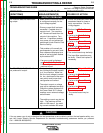
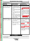
11
12
CAN communication bus off.
User interface time out error.
Probably due to excessive number of communication errors.
UI is no longer responding to the Power Source. The most
likely cause is a fault/bad connection in the communication
leads or control cable.
21
Unprogrammed weld mode.
Contact the service department for instructions on reloading
the Welding Software.
22
Empty weld table.
Contact the service department for instructions on reloading
the Welding Software.
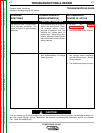
23
Weld table checksum error.
Contact the service department for instructions on reloading
the Welding Software.
31
Primary overcurrent error.
Excessive Primary current present. May be related to a
short in the main transformer or output rectifier.
32
Capacitor “A” under voltage.
Low voltage on the main capacitors. May be caused by
improper input configuration.
33
Capacitor “B” under voltage.
When accompanied by an overvoltage error on the same
side, it indicates no capacitor voltage present on that side,
and is usually the result of an open or short in the primary
side of the machine.
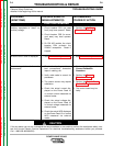
34
Capacitor “A” overvoltage.
Excessive voltage on the main capacitors. May be caused
by improper input configuration.
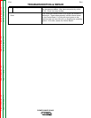
35 Capacitor “B” overvoltage.
When accompanied by an under voltage error on the same
side, it indicates no capacitor voltage present on that side,
and is usually the result of an open or short in the primary
side of the machine.
36 Thermal error.
Indicates over temperature. Usually accompanied by ther-
mal LED. Check fan operation. Be sure process does not
exceed duty cycle limit of the machine.
37 Softstart error.
Capacitor precharge failed. Usually accompanied by codes
32-35.
41 Secondary overcurrent error
The secondary (weld) current limit has been exceeded.
When this occurs the machine output will phase back to
100 amps, typically resulting in a condition referred to as
“noodle welding”
NOTE: The secondary limit is 570 for the standard stud, and
325 amps for all single phase operation.