


Return to Section TOC Return to Section TOC Return to Section TOC Return to Section TOC
Return to Master TOC Return to Master TOC Return to Master TOC Return to Master TOC
POWER WAVE 355/405
TROUBLESHOOTING & REPAIR
F-8 F-8
Observe Safety Guidelines
TROUBLESHOOTING GUIDE
detailed in the beginning of this manual.
CAUTION
If for any reason you do not understand the test procedures or are unable to perform the test/repairs safely, con-
tact the Lincoln Electric Service Department for electrical troubleshooting assistance before you proceed.
Call 1-800-833-9353(WELD).
PROBLEMS
(SYMPTOMS)
POSSIBLE AREAS OF
MISADJUSTMENT(S)
RECOMMENDED
COURSE OF ACTION
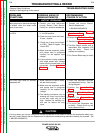
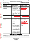
FUNCTION PROBLEMS
Auxiliary receptacle is “dead” no
auxiliary voltage.
1. Circuit breaker CB1 (on case
front) may have opened. Reset.
2. Circuit breaker CB3 (in recon-
nect area) may have opened.
Reset.
3. On PW 405 models, the circuit
breaker CB4 protects the
220VAC receptacle. Reset if
tripped.
1. Perform the Auxiliary
Transformer Test.
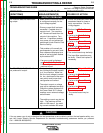
A fault or error code is displayed. 1. See Fault Code Explanations. 1. See Fault Code Explanations.
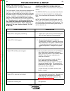
General degradation of the weld
performance.
1. Check for feeding problems,
bad connections, excessive
loops in cabling, etc.
2. Verify weld mode is correct for
processes.
3. The power source may require
calibration.
4. Check the actual current dis-
played on the Power Feed 10
vs. actual current measured via
external meter.
5. Check the actual voltage dis-
played on the Power Feed 10
vs. actual voltage measured via
external meter.
6. Check the actual WFS displayed
on the Power Feed 10 vs. actual
WFS measured via external
meter.
1. Perform the Voltage and
Current Calibration
Procedure.
2. Perform the Current
Transducer Test.
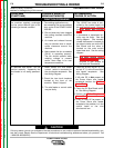
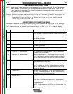
2. Perform the Output Diode
Module Test.
5. The control board may be
faulty.