


Return to Section TOC Return to Section TOC Return to Section TOC Return to Section TOC
Return to Master TOC Return to Master TOC Return to Master TOC Return to Master TOC
POWER WAVE 355/405
TROUBLESHOOTING & REPAIR
F-4 F-4
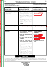
Observe Safety Guidelines TROUBLESHOOTING GUIDE
detailed in the beginning of this manual.
CAUTION
If for any reason you do not understand the test procedures or are unable to perform the test/repairs safely, con-
tact the Lincoln Electric Service Department for electrical troubleshooting assistance before you proceed. Call
1-800-833-9353(WELD).
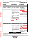
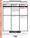
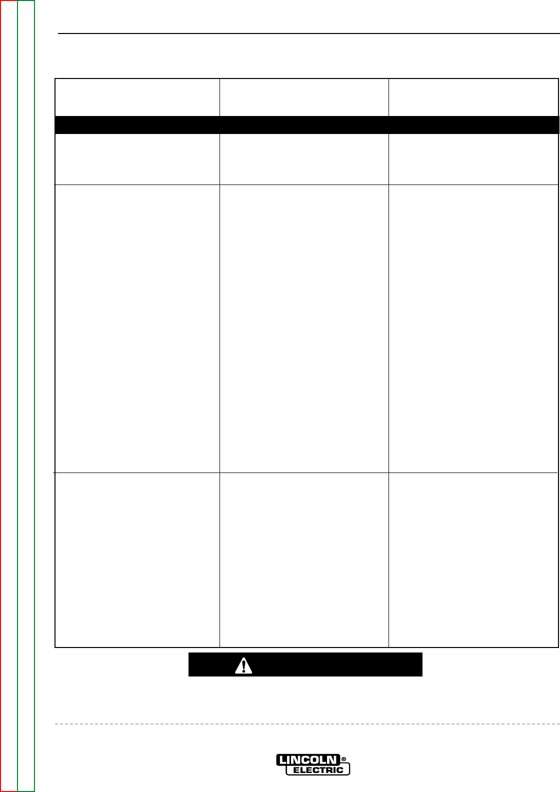
PROBLEMS
(SYMPTOMS)
POSSIBLE AREAS OF
MISADJUSTMENT(S)
RECOMMENDED
COURSE OF ACTION
OUTPUT PROBLEMS
Major physical or electrical damage
is evident when the sheet metal
cover is removed.
1. Contact your local authorized
Lincoln Electric Field Service
Facility for technical assistance.
1. Contact the Lincoln Electric
Service Department,
1-800-833-9353(WELD).
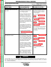
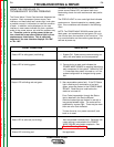
The machine is dead—no output—
no LED’s.
1. Make sure the input line switch is
in the ON position.
2. Check the main input line fuses.
If open , replace.
3. Check the 15 amp circuit break-
er (CB1). Reset if tripped. Also
check CB3.
4. Make sure the reconnect switch
and jumper lead is configured
correctly for the applied input
voltage.
5. If the machine is being operated
with single phase input voltage
make sure the correct lead is not
connected. See the Installation
Section.
1. Perform the Auxiliary
Transformer Test.
2. Perform the DC Bus Board Test.
2. Perform the Power Board Test.
3. The Bus Board rectifier and or
associated filter capacitor (C5)
may be faulty. Check and
replace as necessary.
4. The Control Board may be faulty.
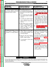
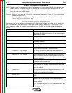
The main input fuses (or breaker)
repeatedly fail.
1. Make certain the fuses or break-
ers are sized properly.
2. Make sure the reconnect switch
and jumper lead is configured
correctly for the applied input
voltage.
3. The welding procedure may be
drawing too much input current
or the duty cycle may be too
high. Reduce the welding cur-
rent and /or reduce the duty
cycle.
1. Check the reconnect switches
and associated wiring. See the
Wiring Diagram.
2. Perform the Input Rectifier
Test.
3. Perform the Main Switch Board
Test.
4. Perform the Output Diode
Module Test.
5. The Input Filter Capacitors may
be faulty. Check, and if any are
faulty replace all four.