


INSTALLATION
A-11 A-11
POWER WAVE 355/405
Return to Section TOC Return to Section TOC Return to Section TOC Return to Section TOC
Return to Master TOC Return to Master TOC Return to Master TOC Return to Master TOC
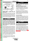
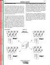
WELDING WITH MULTIPLE POWER
WAVES
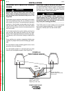
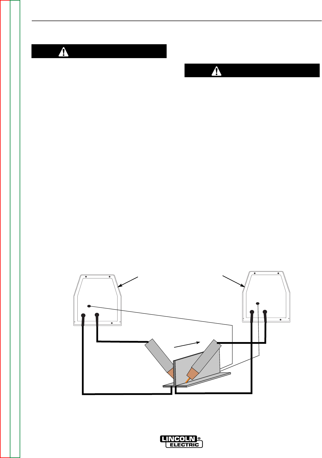
Special care must be taken when more than one
Power Wave is welding simultaneously on a single
part. Arc blow and arc interference may occur or be
magnified.
Each power source requires a work lead from the work
stud to the welding fixture. Do not combine all of the
work leads into one lead. The welding travel directions
should be in the direction moving away from the work
lead as shown below. Connect all of the work sense
leads from each power source to the work piece at the
end of the weld.
For the best results when pulse welding, set the wire
size and wire feed speed the same for all the Power
Waves. When these parameters are identical, the puls-
ing frequency will be the same, helping to stabilize the
arcs.
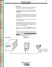
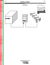
Every welding gun requires a separate shielding gas
regulator for proper flow rate and shielding gas cover-
age.
Do not attempt to supply shielding gas for two or more
guns from only one regulator.
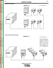
If an anti-spatter system is in use then each gun must
have its own anti-spatter system. (See Figure A.6)
CAUTION
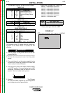
CONTROL CABLE SPECIFICATIONS
It is recommended that genuine Lincoln control cables
be used at all times. Lincoln cables are specifically
designed for the communication and power needs of
the Power Wave / Power Feed system.
The use of non-standard cables, especially in
lengths greater than 25 feet, can lead to communi-
cation problems (system shutdowns), poor motor
acceleration (poor arc starting) and low wire dri-
ving force (wire feeding problems).
------------------------------------------------------------------------
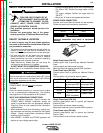
The K1543 series of control cables can be connected
end to end for ease of extension. Do not exceed
more than 100 feet (30.5 m) total control cable
length.
CAUTION
Connect All Work
Sense Leads at the End
of the Joint
Connect All Welding
Work Leads at the
Beginning of the Joint
Travel
Direction
POWER WAVE 355/405
POWER WAVE 355/405
TWO POWER WAVES
FIGURE A.6