


TROUBLESHOOTING & REPAIR
F-63 F-63
POWER WAVE 355
Return to Section TOC Return to Section TOC Return to Section TOC Return to Section TOC
Return to Master TOC Return to Master TOC Return to Master TOC Return to Master TOC
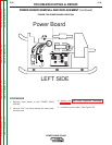
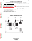
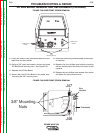
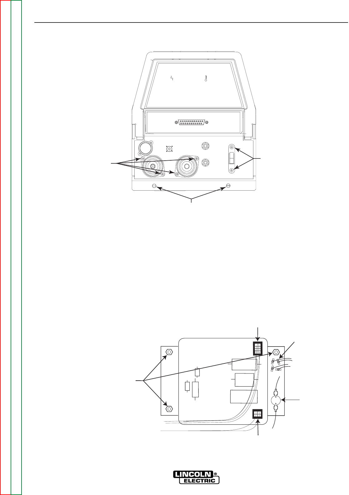
9. Label and remove two thermostat leads and four
leads from the bus rectifier.
10. Using a 3/8” open end wrench, remove the three
DC Bus Board mounting nuts. See Figure F.29.
11. Replace the DC Bus Board.
12. Secure the new DC Bus Board in its proper loca-
tion using the 3/8” mounting nuts.
13. Reconnect previously removed leads to their prop-
er locations.
14. Replace the four phillips head screws mounting
the two welder output terminals to the front of the
machine.
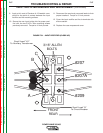
15. Replace the two phillips head screws from above
and below the input power switch.
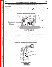
DC BUS BOARD REMOVAL AND REPLACEMENT (Continued)
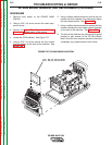
STATUS THERMAL
_
+
Phillips Head
Screws
Phillips Head
Screws
5/16"
Mounting Screws
FIGURE F.28 CASE FRONT SCREW REMOVAL
FIGURE F.29 CASE FRONT SCREW REMOVAL
L11078-1
J46
J47
3/8" Mounting
Nuts
Thermostat
Bus
Rectifier