


OPERATION
B-3 B-3
POWER WAVE 355/405
Return to Section TOC Return to Section TOC Return to Section TOC Return to Section TOC
Return to Master TOC Return to Master TOC Return to Master TOC Return to Master TOC
POWER WAVE 355/405 – Semi-Automatic
Operation
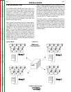
Semi Automatic Power Waves can only be used with
Linc-Net compatible Power Feed semi-automatic wire
feeders. In addition, the Power Feed semi-automatic
wire feeders may require optional equipment to access
certain weld modes in the Power Wave. Other models
of Lincoln feeders, or any models of non-Lincoln wire
feeders, cannot be used.
All welding programs and procedures are selected
through the Power Feed semi-automatic user interface
REQUIRED EQUIPMENT
Any Linc-Net compatible semi-automatic wire feeding
equipment. Specifically, the semi-automatic Power
Feed family (PF-10, PF-10X2, PF-11).
LIMITATIONS
• Only Linc-Net compatible Power Feed semi-automat-
ic wire feeders and users interfaces may be used.
Other Lincoln wire feeders or non-Lincoln wire feed-
ers cannot be used.
• POWER WAVE 355/405 Output Limitations
The POWER WAVE 355/405 will support maximum
average output current of 350 Amps @ 60% duty
cycle.
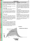
DUTY CYCLE AND TIME PERIOD
The duty cycle is based upon a ten minute period. A
60% duty cycle represents 6 minutes of welding and 4
minutes of idling in a ten minute period.
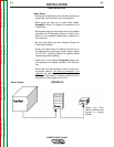
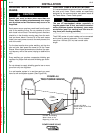
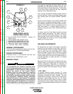
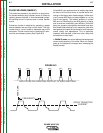
CASE FRONT CONTROLS
All operator controls and adjustments are located on
the case front of the Power Wave. (See Figure B.1)
1. POWER SWITCH: Controls input power to the
Power Wave.
2. STATUS LIGHT: A two color light that indicates sys-
tem errors. Normal operation is a steady green
light. Error conditions are indicated, per table B.1.
NOTE: The POWER WAVE 355/405 status light will
flash green, and sometimes red and green, for up to
one minute when the machine is first turned on. This is
a normal situation as the machine goes through a self
test at power up.
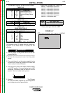
TABLE B.1
Light
Condition
Steady Green
Blinking
Green
Alternating
Green and
Red
Steady Red
Blinking Red
Meaning
System OK. Power source communicating normal-
ly with wire feeder and its components.
Occurs during a reset, and indicates the
POWER WAVE 355/405 is mapping (identi-
fying) each component in the system.
Normal for first 1-10 seconds after power is
turned on, or if the system configuration is
changed during operation
Non-recoverable system fault. If the PW
Status light is flashing any combination of
red and green, errors are present in the
POWER WAVE 355/405. Read the error
code before the machine is turned off.
Error Code interpretation through the Status
light is detailed in the LED Status Chart.
Individual code digits are flashed in red with
a long pause between digits. If more than
one code is present, the codes will be sepa-
rated by a green light.
To clear the error, turn power source off, and
back on to reset.
Non recoverable hardware fault. Generally
indicates nothing is connected to the
POWER WAVE 355/405 wire feeder recep-
tacle. See Trouble Shooting Section.
Not applicable.
3. HIGH TEMPERATURE LIGHT (thermal overload):
A yellow light that comes on when an over temper-
ature situation occurs. Output is disabled and the
fan continues to run, until the machine cools down.
When cool, the light goes out and output is enabled.
4. CB1 WIRE FEEDER CIRCUIT BREAKER:
Protects 40 volt DC wire feeder power supply.