


INSTALLATION
A-8 A-8
POWER WAVE 355/405
Return to Section TOC Return to Section TOC Return to Section TOC Return to Section TOC
Return to Master TOC Return to Master TOC Return to Master TOC Return to Master TOC
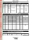
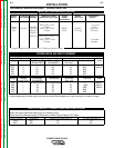
SYSTEM SET-UP
Basic Rules
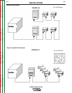
• Each group is required to have one user interface. No
group may have more than one user interface.
• Each group can have up to seven Feed Heads.
Exception: Group 3 is limited to a maximum of six
Feed Heads.
• Each system has only one power source. For network
purposes, the PS belongs to Group 3, which is why
group 3 is only allowed 6 feed heads in addition it’s
user interface.
• No two feed heads can have identical Group and
Feed Head numbers.
• Group and Feed Head ID numbers must be set on
the appropriate dip switches at each node. Consult
the PF-10/11 Instruction Manual for specific details
regarding dip switch settings.
• Feed head “0” not allowed. Exception: Simple sys-
tem ignores all ID numbers, therefore “FH0” will func-
tion.
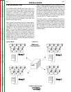
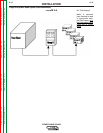
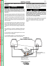
• Each node must be connected to the Linc-Net com-
munication network. The order of connection is not
important, as each node is identified by it’s unique
Group and Feed Head ID number as defined on it’s
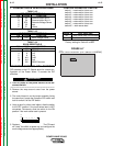
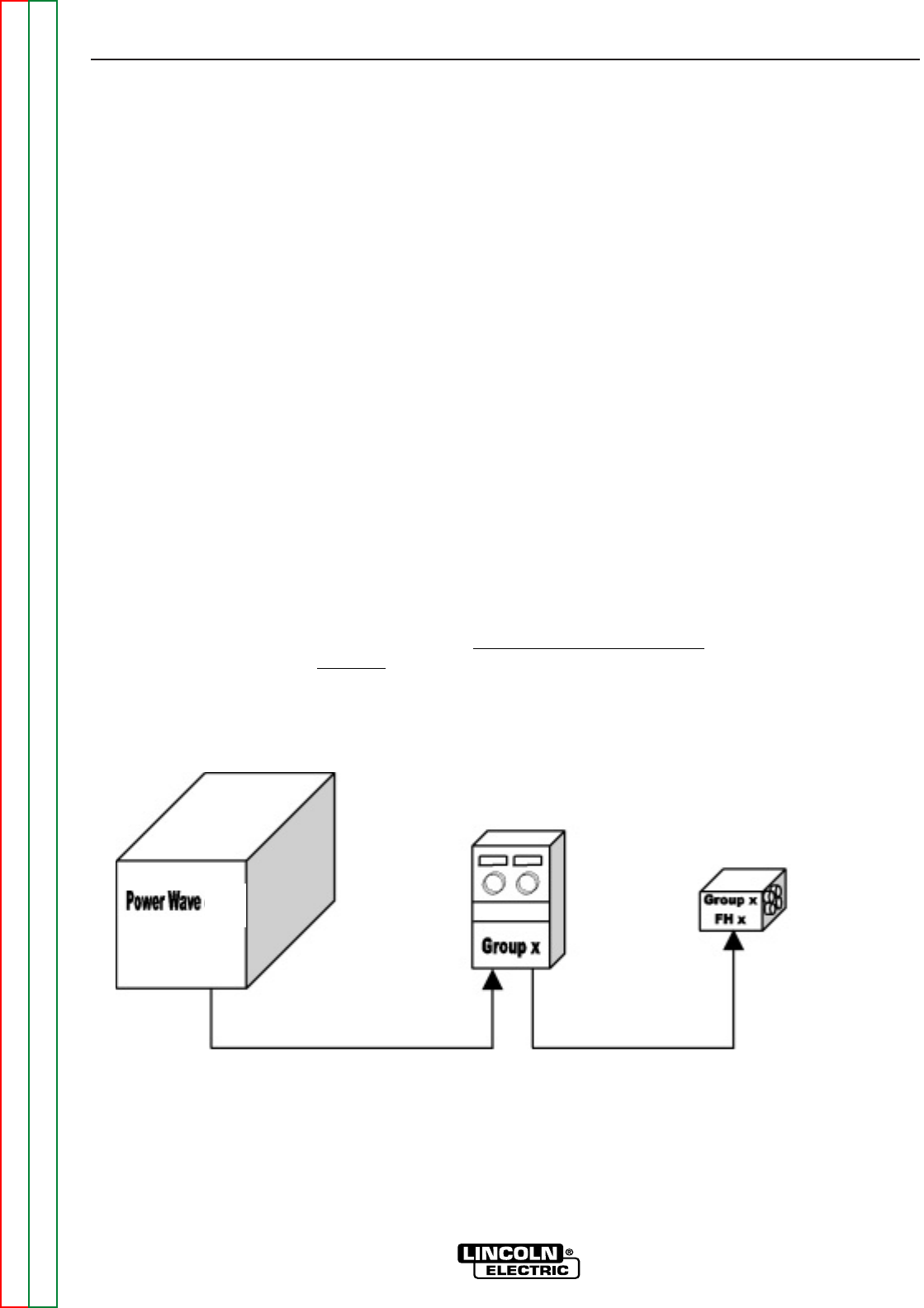
dip switches. See Figures A.2 thru A.5.
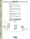
FIGURE A.2
Simple System
Group and Feed
Head ID numbers are
ignored in a simple
system.