


THEORY OF OPERATION
E-4 E-4
POWER WAVE 355/405
Return to Section TOC Return to Section TOC Return to Section TOC Return to Section TOC
Return to Master TOC Return to Master TOC Return to Master TOC Return to Master TOC
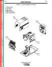
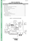
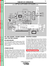
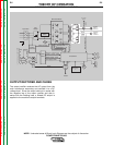
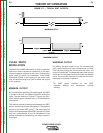
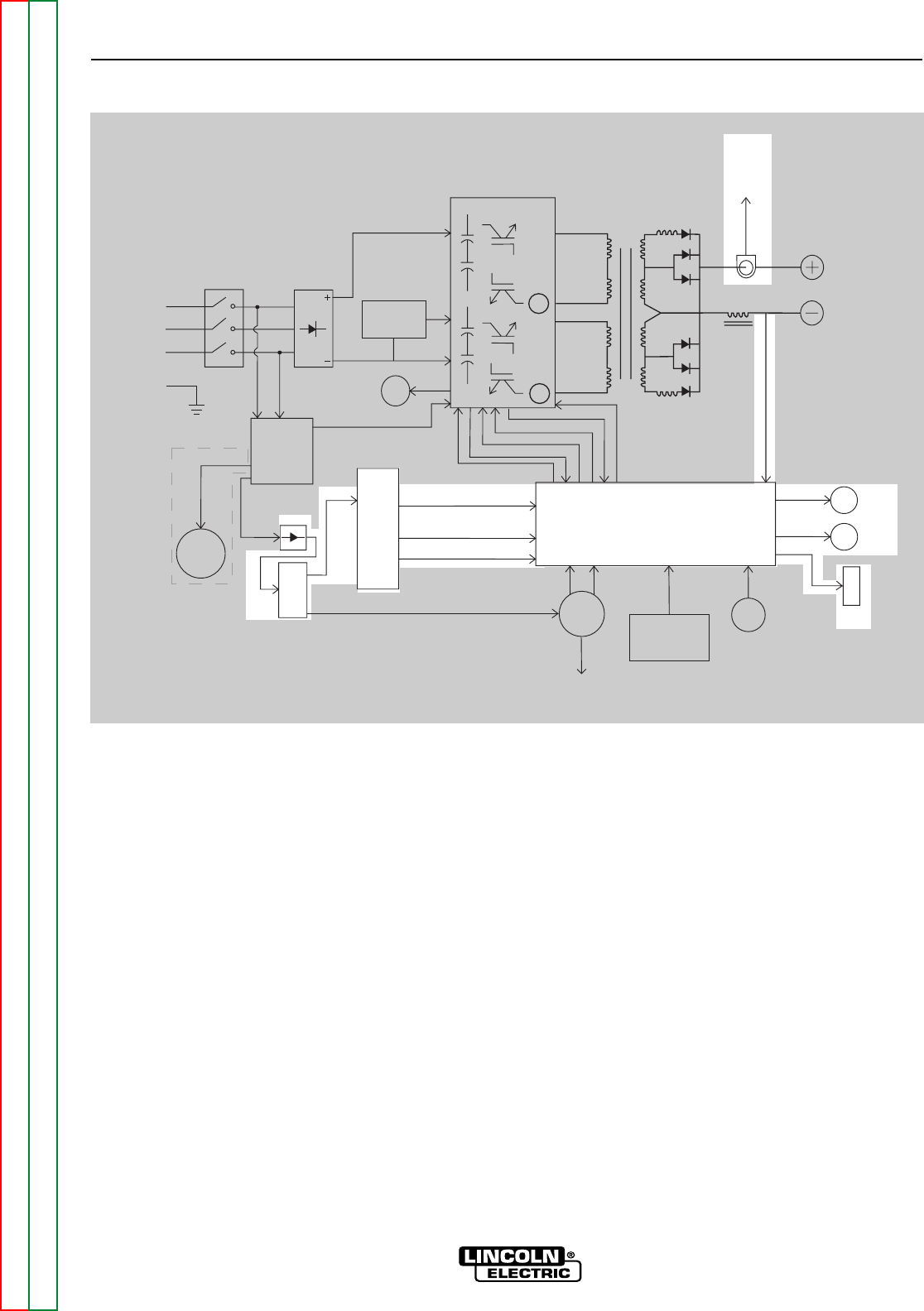
FIGURE E.4 – POWER BOARD, CONTROL BOARD
AND SERIAL PERIPHERAL INTERFACE (SPI) COMMUNICATIONS
Control Board
Choke
Positive
Output
Ter minal
Negative
Output
Ter minal
To Control
Board
Current
Feedback
Reconnect
Switch
Output Voltage Sense
Input switch
Input
Rectifier
Auxiliary
Transformer
Fan
Power
Board
220
Receptacle
RS232 Supply +5VDC
Machine Control Supply
+15VDC, -15VDC, +5VDC
40VDC
42VAC
220 VAC
Main Switch Board
115VAC Fan Supply
Fan Control
V/F Capacitor Feedback (2)
Soft Start Control
Input Relay Control
Primary Current Feedback(2)
IGBT Drive S
ignal
Primary
Current
Sensor
Primary
Current
Sensor
{
P
o
w
e
r
W
a
v
e
4
0
5
o
n
l
y
65VAC
DC
Bus
Board
Wire
Feeder
Recp.
40VDC
Can Supply +5VDC
Arc
Link
Electrode
Sense
21 Lead
Voltage
Sense
Recp.
R232
Connector
Yellow
Thermal
LED
Status
Red/Green
LED
Thermostats
2
To
Feeder
DC BUS BOARD, POWER BOARD
AND CONTROL BOARD
DC BUS BOARD
The DC Bus Board receives approximately 65VDC
from the bus board rectifier. The DC Bus Board regu-
lates that 65VDC to a +40VDC supply. This regulated
40VDC is applied to the Power Board and the wire
feed receptacles.
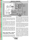
POWER BOARD
The power board, utilizing a switching power supply,
processes the 40VDC input and develops several reg-
ulated positive and negative DC supplies. Three DC
supplies are fed to the control board for machine con-
trol supplies. A +5VDC is used for the RS232 connec-
tion supply. Another +5VDC supply is utilized by the
CAN digital communication circuitry. An over or under
input voltage detection and shutdown circuit is also
part of the power board’s circuitry.
CONTROL BOARD
The Control Board performs the primary interfacing
functions to establish and maintain output control of
the POWER WAVE 355/405. The function generator
and weld files exist within the Control Board hardware
and software. Digital command signals received from
the user interface/feed head and feedback information
received from the current sensor and output voltage
sensing leads, are processed at the control board.
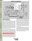
Software within the control board processes the com-
mand and feedback information and sends the appro-
priate pulse width modulation (PWM) signals (See
PULSE WIDTH MODULATION in this section) to the
switch board IGBT’s. In this manner, the digitally con-
trolled high speed welding waveform is created.
In addition, the Control Board monitors the ther-
mostats, the main transformer primary currents and
input filter capacitor voltages. Depending on the fault
condition, the Control Board will activate the thermal
and/or the status light and will disable or reduce the
machine’s output.