


TROUBLESHOOTING AND REPAIR
CURRENT TRANSDUCER TEST (continued)
F-41 F-41
POWER WAVE 355/405
Return to Section TOC Return to Section TOC Return to Section TOC Return to Section TOC
Return to Master TOC Return to Master TOC Return to Master TOC Return to Master TOC
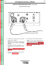
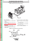
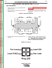
8. Check the feedback voltage from the current
transducer using a resistive load bank and
with the POWER WAVE 355/405 in mode 200.
Mode 200 is a constant current test mode.
This mode can be accessed using a wire feed-
er placed in mode 200 or a laptop computer
and the appropriate software. Apply the grid
load across the output of the POWER WAVE
355/405. Set machine output to 300 amps
and enable WELD TERMINALS. Adjust the
grid load to obtain 300 amps on the external
ammeter and check feedback voltages per
Table F.6.
A. Pin 1 (lead 801) to Pin 6 (lead 806) should
read 2.4 VDC (machine loaded to 300
amps).
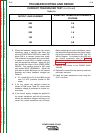
9. If for any reason the machine cannot be
loaded to 300 amps, Table F.6. shows what
feedback voltage is produced at various cur-
rent loads.
10. If the correct supply voltages are applied to
the current transducer, and with the machine
loaded, the feedback voltage is missing or not
correct the current transducer may be faulty.
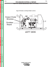
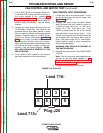
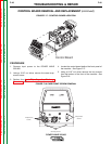
Before replacing the current transducer, check
the leads and plugs between the control board
(J8) and the current transducer (J90). See The
Wiring Diagram. For access to plug J90 and
the current transducer refer to: Current
Transducer Removal and Replacement
Procedure.
11. Remove input power to the POWER WAVE
355/405.
12. Replace the control box top and any cable ties
previously removed.
13. Install the case wraparound cover using the
5/16” nut driver.
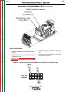
TABLE F.6
OUTPUT LOAD CURRENT
EXPECTED TRANSDUCER FEEDBACK
VOLTAGE
300
250
200
150
100
2.4
2.0
1.6
1.2
0.8