


Section E-1 Section E-1
POWER WAVE 355/405
Theory of Operation .............................................................................................................Section E
General Description ....................................................................................................................E-2
Input Line Voltage, Auxiliary Transformer and Precharge...........................................................E-2
Switch Board and Main Transformer ..........................................................................................E-3
DC Bus Board, Power board and Control Board .......................................................................E-4
Output Rectifier and Choke ........................................................................................................E-5
Thermal Protection .....................................................................................................................E-6
Protective Circuits.......................................................................................................................E-6
Over current Protection ........................................................................................................E-6
Under/Over Voltage Protection ............................................................................................E-6
Insulated Gate Bipolar Transistor (IGBT) Operation ...................................................................E-7
Pulse Width Modulation..............................................................................................................E-8
Minimum/Maximum Output..................................................................................................E-8
TABLE OF CONTENTS
-THEORY OF OPERATION SECTION-
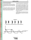
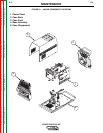
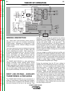
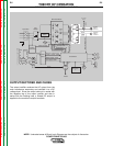
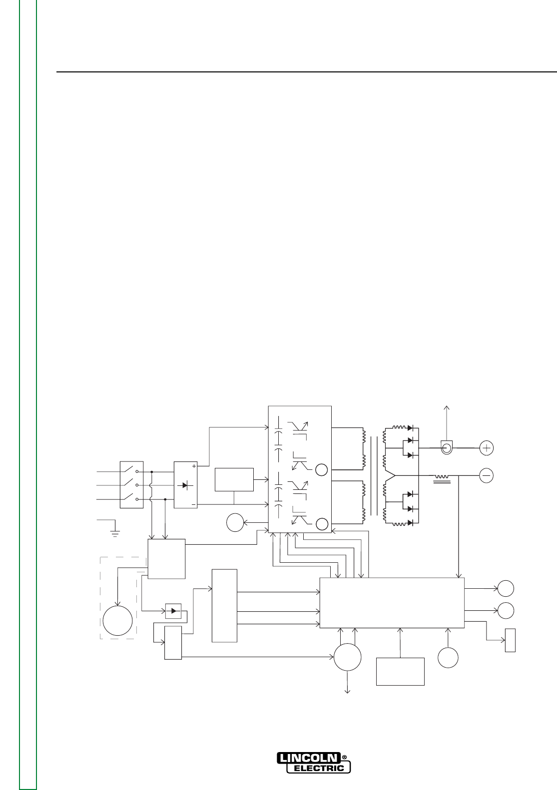
Control Board
Choke
Positive
Output
Terminal
Negative
Output
Terminal
To Control
Board
Current
Feedback
Reconnect
Switch
Output Voltage Sense
Input switch
Input
Rectifier
Auxiliary
Transformer
Fan
Power
Board
220
Receptacle
RS232 Supply +5VDC
Machine Control Supply
+15VDC, -15VDC, +5VDC
40VDC
42VAC
220 VAC
Main Switch Board
115VAC Fan Supply
Fan Control
V/F Capacitor Feedback (2)
Soft Start Control
Input Relay Control
Primary Current Feedback(2)
IGBT Drive S
ignal
Primary
Current
Sensor
Primary
Current
Sensor
{
P
o
w
e
r
W
a
v
e
4
0
5
o
n
l
y
65VAC
DC
Bus
Board
Wire
Feeder
Recp.
40VDC
Can Supply +5VDC
Arc
Link
Electrode
Sense
21 Lead
Voltage
Sense
Recp.
R232
Connector
Yellow
Thermal
LED
Status
Red/Green
LED
Thermostats
2
To
Feeder
FIGURE E.1 – PW-355 BLOCK LOGIC DIAGRAM
Return to Master TOC Return to Master TOC Return to Master TOC Return to Master TOC