


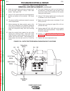
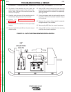

21. Replace the current transducer.
22. Replace the two 3/8” mounting nuts previously
removed.
23. Reconnect plug #J90 to the current transducer.
24. Replace any necessary cable ties previously cut.
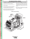
25. From the rear of the machine, replace the heavy
flex lead to the bottom of the output diode
heatsink assembly using a 1/2” wrench. Note:
Don’t forget to include all washers.
26. Replace the output diode heatsink assembly pre-
viously removed using a 3/8” wrench.
Note: Be sure to place insulation in its original
location.
27. Replace leads X2, #20, X4, #40 previously
removed from the two output diode modules.
Torque to 30-40 inch lbs.
28. Perform the Snubber Board Replacement
Procedure.
29. The rear of the machine may now be placed back
into its original position.
30. Using a 3/8” wrench, replace leads #202, #203,
#206, and #207A previously removed from the
reconnect switches.
31. Tighten the metal nut previously removed from the
inside of the rear wall on the back of the machine.
Channel locks may be necessary.
32. Replace the large plastic nut from around input
power line located at the back of the machine.
33. Replace the four leads to the reconnect panel in
their proper locations.
34. Replace the two CB2 circuit breaker leads previ-
ously removed.
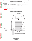
35. Using a 5/16” nut driver, replace the four screws
from the rear assembly.
36. Replace the case wraparound cover.
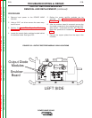
TROUBLESHOOTING & REPAIR
CURRENT TRANSDUCER REMOVAL AND REPLACEMENT (continued)
F-77 F-77
POWER WAVE 355/405
Return to Section TOC Return to Section TOC Return to Section TOC Return to Section TOC
Return to Master TOC Return to Master TOC Return to Master TOC Return to Master TOC