


Return to Section TOC Return to Section TOC Return to Section TOC Return to Section TOC
Return to Master TOC Return to Master TOC Return to Master TOC Return to Master TOC
POWER WAVE 355/405
TROUBLESHOOTING & REPAIR
F-48 F-48
PROCEDURE
1. Remove input power to the POWER WAVE
355/405.
2. Using a 5/16” nut driver remove the case wrap-
around cover.
3. Perform the Input Filter Capacitor Discharge
Procedure detailed earlier in this section.
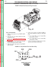
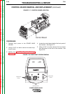
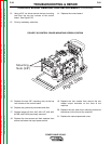
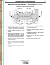
4. Locate the control board behind the front panel of
the machine. See Figure F.17.
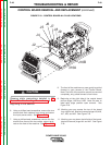
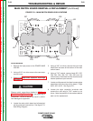
5. Using a 5/16” nut driver remove the two screws
from the bottom of the front of the machine. See
Figure F.18.
CONTROL BOARD REMOVAL AND REPLACEMENT (continued)
ST
ST
ATUS
TUS
THERMAL
THERMAL
_
+
Phillips Head
Screws
Phillips Head
Screws
5/16"
Mounting Screws
FIGURE F.17 - CONTROL BOARD LOCATION
FIGURE F.18 CASE FRONT SCREW REMOVAL
W
A
R
N
IN
G
R
E
M
O
T
E
P
O
W
E
R
O
F
F
O
N
Control Board
STATUS
THERMAL
LINCOLN
ELECTRIC