


Observe static precautions detailed in PC
Board Troubleshooting Procedures at the
beginning of this section.
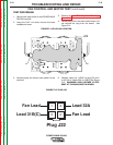
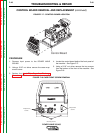
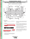
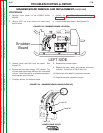
6. Using a phillips head screwdriver remove the two
screws and their washers from above and below
the input power switch. See Figure F.18.
7. Using a phillips head screwdriver remove the four
screws from around the two welder output termi-
nals on the front of the machine. See Figure F.18.
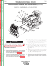
8. The front of the machine may now gently be pulled
forward to gain access to the Control Board.
Note: The front of the machine cannot be removed
completely, only pulled forward a few inches.
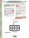
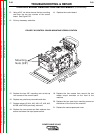
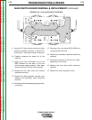
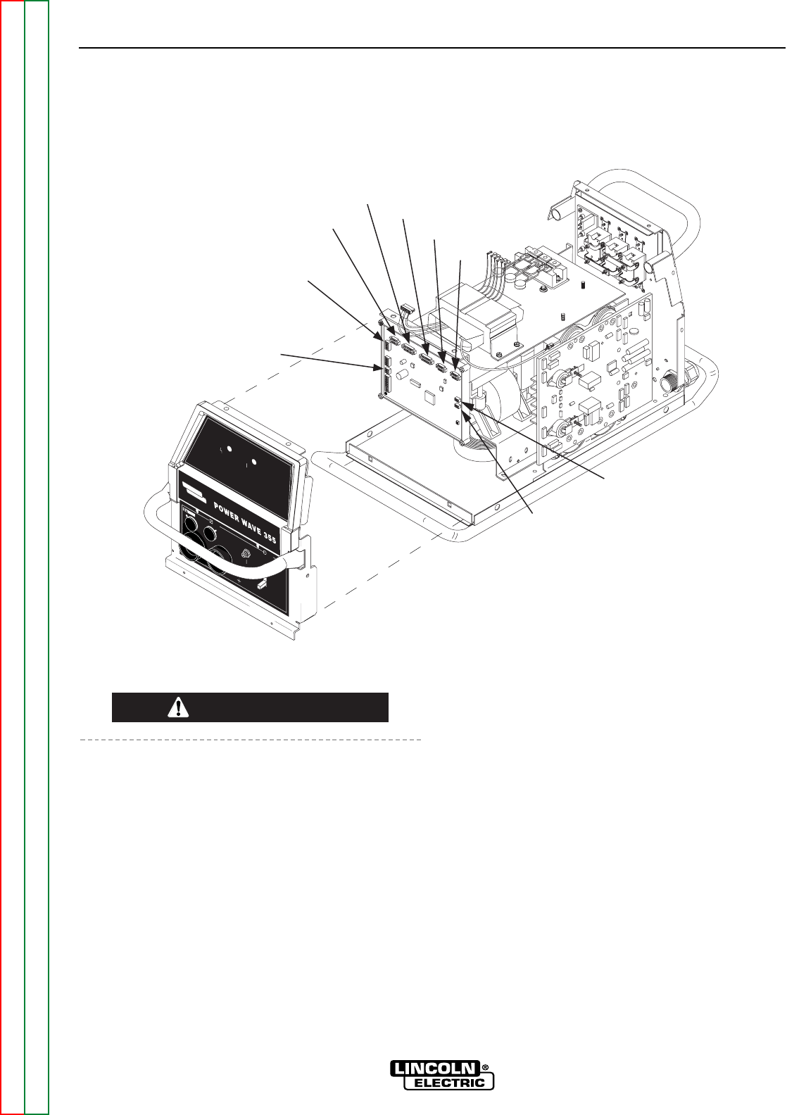
9. Beginning at the right side of the control board
remove plugs J10A and J10B. Note: Be sure to
label each plugs position upon removal. See
Figure F.19.
10. Working your way across the top of the board
from right to left, label and remove plugs #J9, #J8,
#J7, #J6, and #J5. See Figure F.19.
11. Working your way down the left side of the board,
label and remove plugs #J4 and #J2. See Figure
F.19.
CAUTION
POWER WAVE 355/405
Return to Section TOC Return to Section TOC Return to Section TOC Return to Section TOC
Return to Master TOC Return to Master TOC Return to Master TOC Return to Master TOC
TROUBLESHOOTING & REPAIR
F-49 F-49
W
AR
NIN G
R
EM
O
TE
PO
W
ER
O
FF
O
N
STATUS
THERMAL
LINCOLN
ELECTRIC
J2
J4
J5
J6
J7
J8
J9
J10A
J10B
FIGURE F.19 - CONTROL BOARD ALL PLUG LOCATIONS
CONTROL BOARD REMOVAL AND REPLACEMENT (continued)