


POWER WAVE 355/405
Return to Section TOC Return to Section TOC Return to Section TOC Return to Section TOC
Return to Master TOC Return to Master TOC Return to Master TOC Return to Master TOC
TROUBLESHOOTING & REPAIR
F-53 F-53
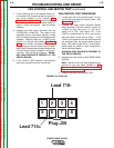
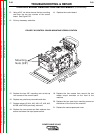
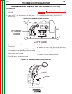
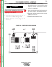
FIGURE F.22 – 3/16” ALLEN BOLT LOCATION
- +
- +
- + - +
3/16" ALLEN BOLTS
MAIN SWITCH BOARD REMOVAL & REPLACEMENT (continued)
9. Using a 3/16” allen wrench remove four allen
bolts and washers as shown in Figure F.22.
At this point, the board is ready for removal.
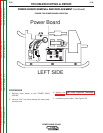
10. Carefully maneuver the board out of the
machine.
11. Apply a thin coat of Penetrox A-13 to the
IGBT heatsinks on the back of the new
switch boards mating surfaces. Note: Keep
compound away from the mounting holes.
12. Replace the four allen bolts and washers
previously removed.
13. Replace the eight capacitor terminal nuts,
washers, and necessary leads previously
removed.
14. Reconnect the three harness plugs previous-
ly removed.
15. Reconnect the nine leads (#201-#209) that
were previously removed.
16. Replace any necessary cable ties previously
removed.
17. Pre-torque all screws to 25 inch lbs. before
tightening to 44 inch lbs.
18. Replace the input lead shield previously
removed.
19. Replace the case wraparound cover.