


POWER WAVE 355/405
Return to Section TOC Return to Section TOC Return to Section TOC Return to Section TOC
Return to Master TOC Return to Master TOC Return to Master TOC Return to Master TOC
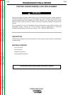
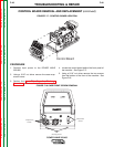
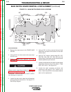
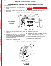
12. Using a 3/8” nut driver remove the two mounting
nuts from the top two corners of the control
board. See Figure F.20.
13. Cut any necessary cable ties.
14. Replace the control board.
15. Replace the two 3/8” mounting nuts at the top
two corners of the control board.
16. Replace any previously removed cable ties.
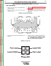
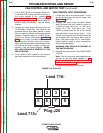
17. Replace plugs #J2, #J4, #J5, #J6, #J7, #J8, #J9,
#J10B, and #J10A previously removed.
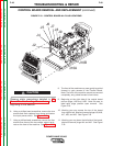
18. Replace the two screws and their washers from
above and below the input power switch.
19. Replace the four screws from around the two
welder output terminals on the front of the
machine.
20. Replace the two case front mounting screws at
the bottom of the front of the machine.
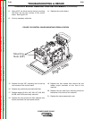
21. Replace the case wraparound cover.
TROUBLESHOOTING & REPAIR
CONTROL BOARD REMOVAL AND REPLACEMENT (continued)
F-50 F-50
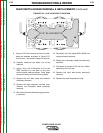
FIGURE F.20 CONTROL BOARD MOUNTING SCREW LOCATION
Right Side
Mounting
Nuts (3/8")