


INSTALLATION
A-6 A-6
POWER WAVE 355/405
Return to Section TOC Return to Section TOC Return to Section TOC Return to Section TOC
Return to Master TOC Return to Master TOC Return to Master TOC Return to Master TOC
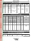
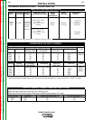
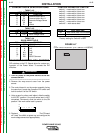
Enable the voltage sense leads as follows:
TABLE A.1
Process Electrode Voltage Work Voltage
Sensing 67 lead * Sensing 21 lead
GMAW 67 lead required 21 lead optional
GMAW-P
67 lead required 21 lead optional
FCAW 67 lead required 21 lead optional
GTAW
Voltage sense at studs Voltage sense at studs
GMAW
Voltage sense at studs Voltage sense at studs
SAW 67 lead required 21 lead optional
CAC-C
Voltage sense at studs Voltage sense at studs
* The electrode voltage 67 sense lead is integral to the
control cable to the wire feeder.
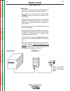
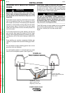
Work Voltage Sensing
The standard POWER WAVE 355/405 default to the
work stud (work sense lead disabled)
For processes requiring work voltage sensing, connect
the (21) work voltage sense lead (K940) from the
Power Wave work sense lead receptacle to the work
piece. Attach the sense lead to the work piece as close
to the weld as practical, but not in the return current
path. Enable the work voltage sensing in the Power
Wave as follows:
• Do not touch electrically live parts or
electrodes with your skin or wet
clothing.
• Insulate yourself from the work and
ground.
• Always wear dry insulating gloves.
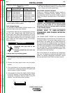
1. Turn off power to the power source at the disconnect
switch.
2. Remove the wrap around cover from the power
source.
3. The control board is on the center assembly facing
the case front. Locate the 8-position DIP switch and
look for switch 8 of the DIP switch.
4. Using a pencil or other small object, slide the switch
to the OFF position if the work sense lead is NOT
connected. Conversely, slide the switch to the ON
position if the work sense lead is present.
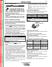
WARNING
O
N
12345678
5. Replace the wrap around and screws. The PC board
will “read” the switch at power up, and configure the
work voltage sense lead appropriately.
ELECTRODE VOLTAGE SENSING
Enabling or disabling electrode voltage sensing is
automatically configured through software. The 67
electrode sense lead is internal to the cable to the wire
feeder and always connected when a wire feeder is
present.
CAUTION
Important: The electrode polarity must be config-
ured at the feed head for all semi-automatic
processes. Failure to do so may result in extreme-
ly high welding outputs.
------------------------------------------------------------------------
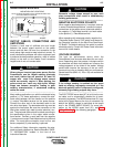
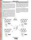
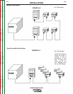
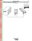
POWER WAVE TO SEMI-AUTOMATIC
POWERFEED WIRE FEEDER INTERCON-
NECTIONS
The POWER WAVE 355/405 and semi-automatic
PowerFeed family communicate via a 5 conductor con-
trol cable (K1543). The control cable consists of two
power leads, one twisted pair for digital communica-
tion, and one lead for voltage sensing. The cables are
designed to be connected end to end for ease of exten-
sion. The output receptacle on the POWER WAVE 405
is on the case front. The input receptacle on the Power
Feed is typically located at the back of the feeder, or on
the bottom of the user interface.
Due to the flexibility of the platform the configuration
may vary. The following is a general description of the
system. For specific configuration information, consult
the semi-automatic Power Feed instruction manual.