


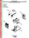
SWITCH BOARD &
MAIN TRANSFORMER
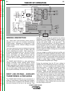
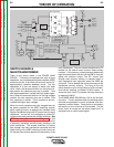
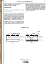
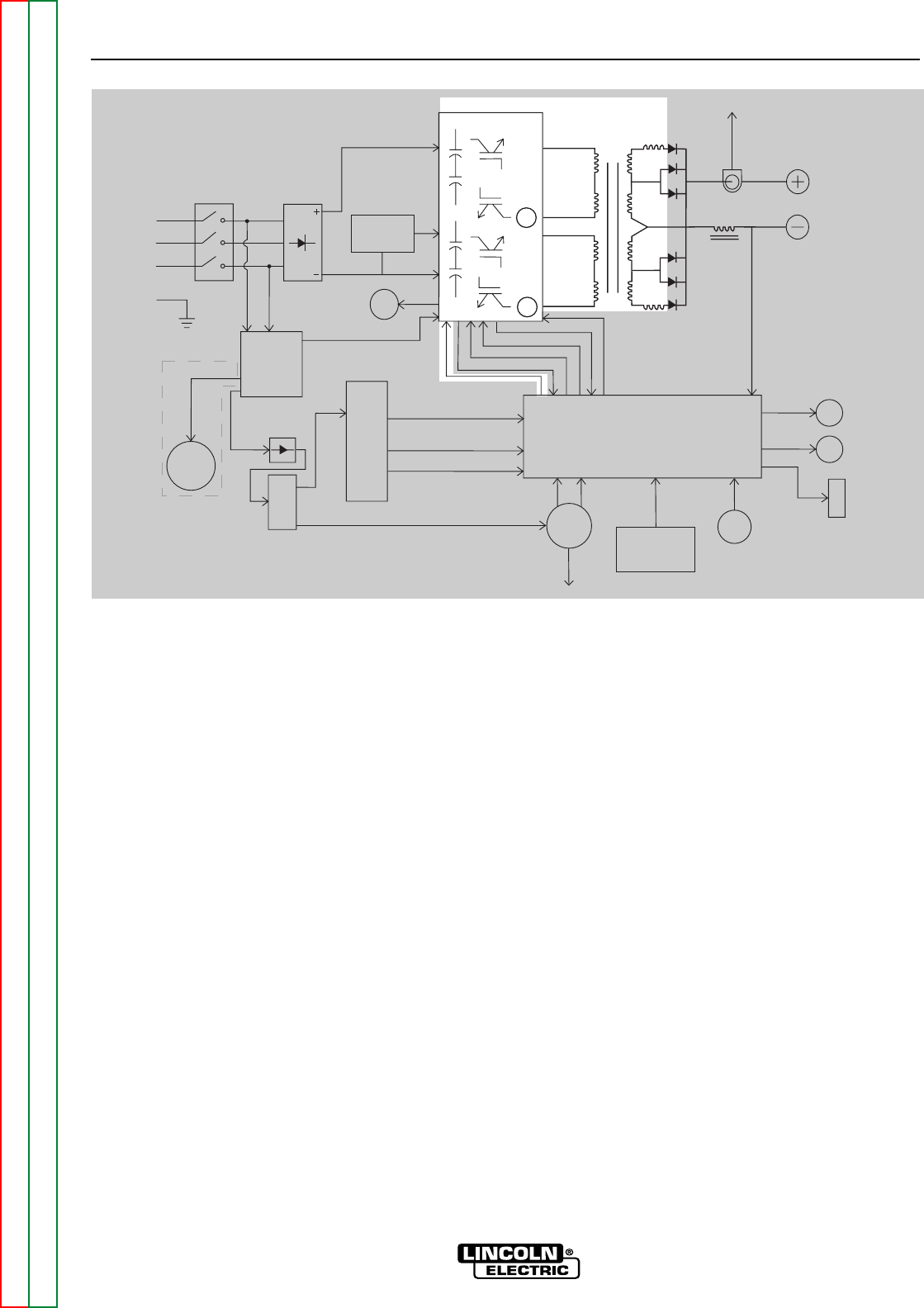
There is one switch board in the POWER WAVE
355/405. This board incorporates two pairs of input
capacitors, two insulated gate bipolar transistor (IGBT)
switching circuits, a fan motor drive circuit, and a volt-
age/frequency capacitor feedback circuit. The two
capacitors in a pair are always in series with each
other. When the reconnect switch is in the lower volt-
age position the capacitor pairs are in parallel . Thus
two series capacitors in parallel with two series capac-
itors. When the reconnect switch is in the high voltage
position the two capacitor pairs are in series. Thus
four capacitors in series. This is required to accom-
modate the higher input voltages.
When the input capacitors are fully charged they act
as power supplies for the IGBT switching circuits.
When welding output is required the Insulated Gate
Bipolar Transistors switch the DC power from the input
capacitors, "on and off" thus supplying a pulsed DC
current to the main transformer primary windings. See
IGBT Operation Discussion and Diagrams in this
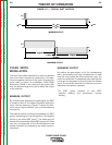
section. Each IGBT switching circuit feeds current to
a separate, oppositely wound primary winding in the
main transformer. The reverse directions of current
flow through the main transformer primaries and the
offset timing of the IGBT switching circuits induce an
AC square wave output signal at the secondary of the
main transformer. The two current transformers (CT)
located on the switch board monitor these primary
currents. If the primary currents become abnormally
high the control board will shut off the IGBTs, thus dis-
abling the machine output. The DC current flow
through each primary winding is clamped back to
each respective input capacitor when the IGBTs are
turned off. This is needed due to the inductance of the
transformer primary winding. The firing of the two
switch boards occurs during halves of a 50 microsec-
ond interval, creating a constant 20 KHZ output. In
some low open circuit Tig modes the firing frequency
is reduced to 5KHZ.
The POWER WAVE 355/405 has a F.A.N. fan as need-
ed circuit. The fan operates when the welding output
terminals are energized or when a thermal over tem-
perature condition exists. Once the fan is activated it
will remain on for a minimum of five minutes. The fan
driver circuit is housed on the switch board but it is
activated from a control board signal.
THEORY OF OPERATION
E-3 E-3
POWER WAVE 355/405
Return to Section TOC Return to Section TOC Return to Section TOC Return to Section TOC
Return to Master TOC Return to Master TOC Return to Master TOC Return to Master TOC
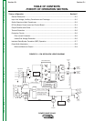
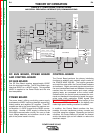
FIGURE E.3 – SWITCH BOARD & MAIN TRANSFORMER
Control Board
Choke
Positive
Output
Ter minal
Negative
Output
Ter minal
To Control
Board
Current
Feedback
Reconnect
Switch
Output Voltage Sense
Input switch
Input
Rectifier
Auxiliary
Transformer
Fan
Power
Board
220
Receptacle
RS232 Supply +5VDC
Machine Control Supply
+15VDC, -15VDC, +5VDC
40VDC
42VAC
220 VAC
Main Switch Board
115VAC Fan Supply
Fan Control
V/F Capacitor Feedback (2)
Soft Start Control
Input Relay Control
Primary Current Feedback(2)
IGBT Drive Signal
Primary
Current
Sensor
Primary
Current
Sensor
{
P
o
w
e
r
W
a
v
e
4
0
5
o
n
l
y
65VAC
DC
Bus
Board
Wire
Feeder
Recp.
40VDC
Can Supply +5VDC
Arc
Link
Electrode
Sense
21 Lead
Voltage
Sense
Recp.
R232
Connector
Yellow
Thermal
LED
Status
Red/Green
LED
Thermostats
2
To