


Return to Section TOC Return to Section TOC Return to Section TOC Return to Section TOC
Return to Master TOC Return to Master TOC Return to Master TOC Return to Master TOC
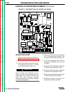
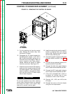
WIRE DRIVE ASSEMBLY AND COMPONENTS REPLACEMENT
(continued)
TROUBLESHOOTING AND REPAIRF-38
LN-7 GMA WIRE FEEDER
REPAIR PROCEDURE
1. Remove the cover from the control by
removing the four 5/16 in. screws from
the top and side of the unit.
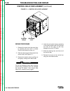
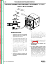
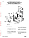
2. Cut the two tie wraps securing the feed
motor leads to the main wire harness
and disconnect the two motor leads
from terminals #539 and #541 on the
control PC board. Refer to Figure F.12.
3. Remove the hex nut securing the motor
ground lead to the case of the control
box. Refer to Figure F.12. Remove the
motor ground lead and reinstall the hex
nut. Do not remove the second ground
wire from the terminal. Feed the three
motor leads through the case of the
control box to the wire drive
compartment.
4. Remove the swing arm assembly per
the Swing Arm Assembly Replacement
procedure.
5. Remove the hex head bolt in the bottom
of the control box which holds the wire
drive assembly to the case. Remove
the two hex head bolts in the bottom of
the wire drive compartment. On the
four-roll feeders, these bolts also have
flat washers and lockwashers.
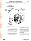
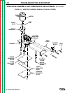
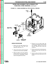
6. Remove the straight head screw that
secures lead #567 to the contact block.
See Figure F.13.
7. Remove the wire drive assembly from
the wire feeder.
8. On two-roll feeders, remove the two
hex head bolts, lockwashers, and flat
washers that secure the contact block
to the wire drive assembly. Remove the
contact block, and locator bushing. On
four-roll wire feeders, remove the hex
head bolt, lockwashers, and flat
washer. Remove the hex nut,
lockwasher, and flat washer from the
bent J-bolt. Remove the contact block,
locator bushing, and bent J-bolt.
539(W) 541(B)
MOTOR
GROUND LEAD
FIGURE F.12 – MOTOR LEAD REMOVAL.