


Return to Section TOC Return to Section TOC Return to Section TOC Return to Section TOC
Return to Master TOC Return to Master TOC Return to Master TOC Return to Master TOC
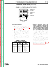
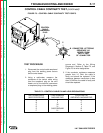
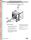
CONTROL
CABLE
AMPHENOL
PLUG
C
D
E
F
A
B
CONNECTOR LETTERING
SEQUENCE AS
VIEWED FROM
CAVITY END
OF CONNECTOR
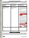
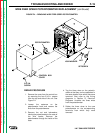
TEST PROCEDURE
1. Disconnect the control cable amphenol
plug from the welding power source
and the wire feeder.
2. Using a multimeter, measure the
resistance of the control cable wiring
from the amphenol plug on the wire
feeder end to the terminal connectors
or amphenol plug on the welding power
source end. Refer to the Wiring
Diagrams in Section G, Table F.2, and
Figure F.3 for wire designations.
3. If the conductor resistance measures
greater than 1.0 Ohm, the cable is
faulty and should be replaced. If the
resistance between conductors is less
than 0.5 MOhm, the cable is faulty and
should be replaced.
TROUBLESHOOTING AND REPAIR F-17
LN-7 GMA WIRE FEEDER
CONTROL CABLE CONTINUITY TEST
(continued)
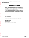
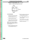
FIGURE F.3 – CONTROL CABLE CONTINUITY TEST POINTS.
TABLE F.2 – CONTROL CABLE PIN AND LEAD DESIGNATIONS
SIX PIN AMPHENOL LEAD NUMBERS FOURTEEN PIN
WIRE FEEDER END MACHINE END AMPHENOL MACHINE END
A4 D
B2 C
C32 A
D31 J
E CASE GROUND B
F21 H