


Return to Section TOC Return to Section TOC Return to Section TOC Return to Section TOC
Return to Master TOC Return to Master TOC Return to Master TOC Return to Master TOC
LN-7 GMA WIRE FEEDER
THEORY OF OPERATION E-5
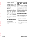
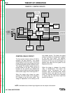
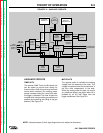
AUXILIARY CIRCUITS
TIMER KITS
The optional GMA Timer and Burnback kits
can be added to provide time delays for
these functions. Both kits provide a burnback
control which maintains the welding power
source contacts closed for a short time after
the trigger is released. The timer kit also has
controls which can provide a gas preflow and
postflow by controlling the timing of the gas
solenoid. See Figure E.4.
METER KITS
The optional meter kit indicates the welding
voltage from the electrode to the work. This
voltage is measured from the contact block in
the wire drive compartment to the work.
While the analog meter kit does not require
any additional power, the digital meter kit is
powered by an 8.8 VAC signal from the
trigger transformer. See Figure E.4.
FIGURE E.4 – AUXILIARY CIRCUITS.
TRIGGER
TRANS-
FORMER
24 VAC
8.8 VAC
115 VAC
CIRCUIT
BREAKER
OPTIONAL
METER KIT
OPTIONAL
TIMER OR
BURNBACK KIT
WIRE
SPEED
CONTROL
CONTROL
BOARD
WIRE DRIVE
MOTOR
5-95 VDC
GUN
TRIGGER
SCR
POWER
CIRCUIT
FROM
WELDING
POWER
SUPPLY
DIODE
RECTIFIER
NETWORK
115 VAC
GAS
SOLENOID
TO WELDING
CONTACTOR
CURRENT
LIMITING
CIRCUIT
115 VAC
GROUND
LEAD
PROTECTOR
CR1
CONTROL
RELAY
24 VDC
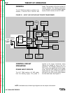
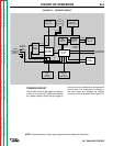
NOTE: Unshaded areas of block logic diagrams are the subject of discussion.