


Return to Section TOC Return to Section TOC Return to Section TOC Return to Section TOC
Return to Master TOC Return to Master TOC Return to Master TOC Return to Master TOC
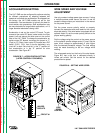
LN-7 GMA WIRE FEEDER
OPERATION B-13
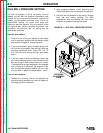
ACCELERATION SETTING
The LN-7 GMA can be configured for optimum starting
for different procedures by selecting between two
speeds of controlled wire acceleration. As shipped from
the factory, the LN-7 GMA models are set for fast
acceleration. Fast acceleration is typically the best for
most smaller wire procedures. Slow acceleration may
be more desirable for long stickout applications, or if a
larger diameter electrode is being used.
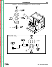
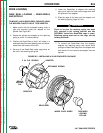
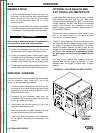
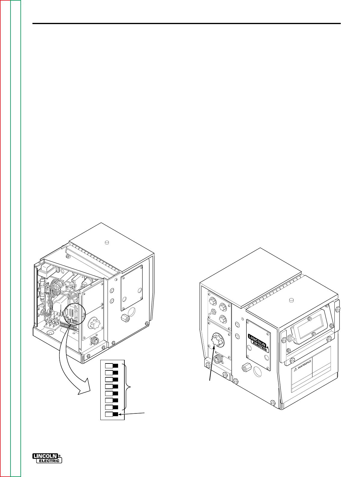
Acceleration is set on the control PC board. To gain
access to the control PC board, make certain the input
power is off and remove the side cover on the control
side of the LN-7 GMA. To change the acceleration on
earlier control PC boards, reconnect the jumper to “F”
(Fast) or “S” (Slow). Later control PC boards use a DIP
switch (S101). S101 has 8 circuits (switches); only
circuit #1 is used. Set circuit #1 in the “F” position for
fast acceleration or in the “S” position for slow
acceleration. See Figure B.7.
FIGURE B.7 – ACCELERATION SETTING
(LATER CONTROL PC BOARDS).
WIRE SPEED AND VOLTAGE
ADJUSTMENT
Use only constant voltage power type sources. If using
a multiple process power source, be sure it is set for
constant voltage output per instructions in the manual
for the power source.
Set the power source polarity switch or properly
connect the electrodes and work leads for the correct
electrode polarity. If the wire feeder is equipped with an
optional meter kit, set the meter polarity switch to the
proper working polarity.
Set the voltage using the control on the power source
or the optional remote voltage control, if used. Set the
open circuit voltage to approximately 2 volts higher
than the desired procedure voltage. The final setting
must be made according to the arc voltage while
welding.
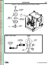
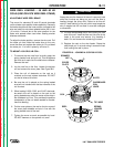
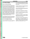
The wire speed control on the front of the wire feeder,
Figure B.8, has a dial that is calibrated directly in
inches per minute. Set the control for the desired
procedure wire speed.
FIGURE B.8 – SETTING WIRE SPEED.
S101
FS
UNUSED
CIRCUITS
CIRCUIT #1
WIRE
SPEED
CONTROL