


Return to Section TOC Return to Section TOC Return to Section TOC Return to Section TOC
Return to Master TOC Return to Master TOC Return to Master TOC Return to Master TOC
LN-7 GMA WIRE FEEDER
OPERATIONB-14
MAKING A WELD
1. Inch the electrode through the gun and cable. For
solid wire, cut the electrode within approximately
3/8 in. of the end of the contact tip. If using cored
wire, cut the electrode within 3/4 in. of the
extension guide.
2. Connect the work cable to the metal to be welded.
The work cable must make good electrical contact
with the work. The work must also be grounded.
When using an open arc process, it is necessary to
use correct eye, head, and body protection.
3. Position the electrode over the joint. The end of
the electrode may be lightly touching the work.
4. Lower your welding helmet. Close the gun trigger
and begin welding. Hold the gun so the contact tip
to work distance gives the correct electrical
stickout as required for the procedure being used.
5. To stop welding, release the gun trigger and then pull
the gun away from the work after the arc goes out.
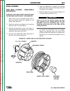
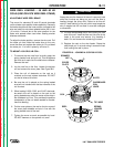
WIRE REEL CHANGING
At the end of a coil, remove the last of the old electrode
from the conductor cable. Either pull it out at the
nozzle, or use the following procedure.
1. Cut off the end of the electrode at the gun end. Do
not break it off by hand. Breaking by hand puts a
slight bend in the wire, making it difficult to pull it
back through the nozzle.
2. Uncouple the gun conductor cable from the
conductor block on the wire feeder drive unit and
lay the gun cable out straight.
3. Using pliers, grip the wire and pull it out of the
cable from the connector end.
4. After the electrode has been removed, connect
the gun conductor back to the wire feeder.
5. Load a new reel of electrode per the instructions
for the specific reel type given previously in this
section.
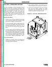
OPTIONAL K416 ANALOG AND
K417 DIGITAL VOLTMETER KITS
Lincoln Specified Procedures give voltmeter readings
taken between the work and the gun cable brass
connection block inside the LN-7 GMA. To match these
voltage readings, the #21 lead should be extended
directly to the work per the instructions on the wire
feeder to power source connection diagrams given in
the Installation Section.
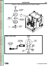
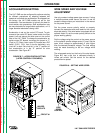
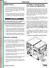
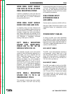
To read volts, set the “Electrode Polarity” switch, Figure
B.9, to the same polarity as the electrode lead
connection to the power source.
The K417 Digital Voltmeter Kit has a hold feature that
will freeze the last arc voltage reading at the moment
the trigger is released to stop welding. This feature
allows the welding operator to easily check the arc
voltage and make adjustments if necessary to match
procedures. For accuracy, it is important to release
the gun trigger and the lift the gun away from the
work.
The hold circuit automatically releases about six
seconds after the gun trigger is released. It is also
released when the trigger is closed again to begin
welding.
FIGURE B.9 – ELECTRODE POLARITY SWITCH.
ELECTRODE
POLARITY
SWITCH
WARNING