


Return to Section TOC Return to Section TOC Return to Section TOC Return to Section TOC
Return to Master TOC Return to Master TOC Return to Master TOC Return to Master TOC
E-6 THEORY OF OPERATION
LN-7 GMA WIRE FEEDER
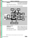
PROTECTIVE CIRCUITS
Protective circuits are designed in to the
LN-7 GMA to detect trouble and shut down
the wire feeder before any damage to the
feeder can result. The wire feeder contains
overload protection for the entire machine, a
current limiting circuit for the feed motor, and
a ground lead protection circuit.
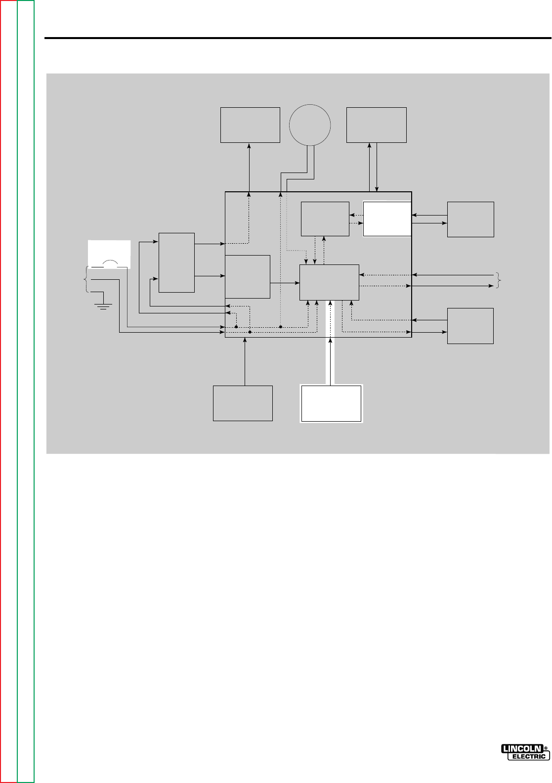
OVERLOAD PROTECTION
The wire feeder is equipped with a circuit
breaker in the 115 Vac input power circuit to
protect the feeder in the event of an electrical
fault. Refer to Figure E.5. If the feeder draws
more than 2.5A, the circuit breaker will trip to
prevent any damage to the wire feeder.
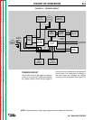
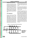
CURRENT LIMITING CIRCUIT
The current limiting circuit limits the current
that is sent to the feed motor. A precision
resistor in line with the feed motor produces
a voltage drop that is directly proportional to
the current draw of the motor. If the signal
exceeds 10VDC, which equates to a 10A
draw from the feed motor, the current limiter
sends a signal to the SCR power circuit to
limit feed motor current to 10A. Refer to
Figure E.5.
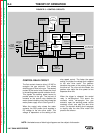
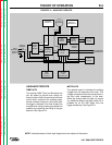
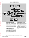
FIGURE E.5 – PROTECTIVE CIRCUITS.
TRIGGER
TRANS-
FORMER
24 VAC
8.8 VAC
115 VAC
CIRCUIT
BREAKER
OPTIONAL
METER KIT
OPTIONAL
TIMER OR
BURNBACK KIT
WIRE
SPEED
CONTROL
CONTROL
BOARD
WIRE DRIVE
MOTOR
5-95 VDC
GUN
TRIGGER
SCR
POWER
CIRCUIT
FROM
WELDING
POWER
SUPPLY
DIODE
RECTIFIER
NETWORK
115 VAC
GAS
SOLENOID
TO WELDING
CONTACTOR
CURRENT
LIMITING
CIRCUIT
115 VAC
GROUND
LEAD
PROTECTOR
CR1
CONTROL
RELAY
24 VDC
NOTE: Unshaded areas of block logic diagrams are the subject of discussion.