


Return to Section TOC Return to Section TOC Return to Section TOC Return to Section TOC
Return to Master TOC Return to Master TOC Return to Master TOC Return to Master TOC
LN-7 GMA WIRE FEEDER
TROUBLESHOOTING AND REPAIR F-39
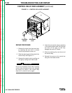
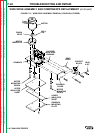
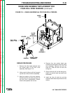
9. On two-roll feeders, remove the three
hex head bolts, lockwashers, and flat
washers from the bottom of the wire
drive assembly. On four-roll feeders,
remove the two straight head screws
from the bottom of the wire drive
assembly. Remove the gearbox
mounting plate and the two insulating
sheets.
10. Remove the covers from the side of the
gearbox by removing the hex head
bolts and lockwashers on each side.
11. Remove the two button head cap
screws and lockwashers from the
bottom of the gearbox. Remove the
three motor mounting screws,
bushings, flat washers and lockwashers
securing the motor to the gearbox. The
two screws on the inside of the gearbox
may be removed by inserting a
screwdriver through the holes that the
button head capscrews were removed
from.
12. Remove the motor and motor insulator
from the gearbox.
13. Remove the roll pin and slide the pinion
gear off the motor shaft.
14. To reassemble the wire drive assembly,
slide the pinion gear onto the motor
shaft and secure in place with the roll
pin. Lubricate the pinion gear with an
even coating of lubricant (part no.
E2322).
15. Apply a thin coating of grease (part no.
E2164) to the mating surfaces of the
motor and motor insulator. Install the
motor and motor insulator on the
gearbox. Secure in place with three
motor mounting screws, lockwashers,
flat washers and bushings. Tighten the
screws to 10 to 12 in-lbs.
16. Install the two button head cap screws
and lockwashers in the bottom of the
gearbox.
17. Coat the sealing surfaces of the
gearbox covers with sealant (part no.
E2225) and install the covers on the
gearbox. Secure in place with two hex
head screws and lockwashers.
18. Install the two insulating sheets and the
gearbox mounting plate and secure in
place with three flat washers,
lockwashers, and hex head bolts. On
four-roll feeders use two straight head
screws.
19. Install the locator bushing and contact
block. Secure in place with two
lockwashers, flat washers, and hex
head bolts. On four-roll feeders, install
the locator bushing, bent J-bolt, and
contact block.
20. Place the wire drive assembly in the
wire drive compartment of the wire
feeder. Ensure the bottom insulating
sheet wraps under the gearbox
mounting plate on both ends.
21. Install lead #567 on the contact block
using the straight head screw.
22. Position the wire drive assembly in the
center of the wire drive compartment
and line up the mounting holes in the
wire drive mounting plate.
23. Install one hex head bolt in the mounting
plate in the control box. For four-roll
feeders, also install a lockwasher and a
flat washer.
24. Install two hex head bolts in the
mounting plate in the wire drive
compartment. For four-roll feeders, also
use two lockwashers and flat washers.
25. Install the swing arm assembly per the
Swing Arm Assembly Replacement
procedure.
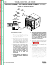
26. Feed the three motor leads through the
hole in the case of the control box.
27. Remove the hex nut from the ground
terminal and install the ground wire.
Secure in place with the hex nut.
28. Install the black motor lead on terminal
#541 of the control PC board, and the
white motor lead on terminal #539.
Secure the motor leads to the main
harness using two tie wraps.
29. Reinstall the cover on the control box
using four hex head screws.
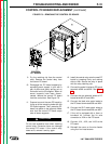
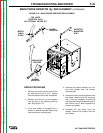
WIRE DRIVE ASSEMBLY AND COMPONENTS REPLACEMENT
(continued)