


Return to Section TOC Return to Section TOC Return to Section TOC Return to Section TOC
Return to Master TOC Return to Master TOC Return to Master TOC Return to Master TOC
TROUBLESHOOTING AND REPAIR
REPAIR PROCEDURE
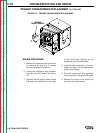
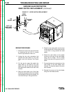
1. Remove the cover from the control box
by removing the four 5/16 in. screws
from the top and side of the unit.
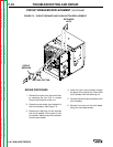
2. Remove the two wires from the back of
the circuit breaker. See Figure F.5.
3. Remove the retaining nut that secures
the circuit breaker to the panel of the
wire feeder. Remove the circuit breaker
from the wire feeder.
4. Install the new circuit breaker through
the panel of the control box. Secure the
circuit breaker with the retaining nut.
5. Connect the two wires to the back of the
circuit breaker.
6. Reinstall the cover on the wire feeder
using four hex head screws.
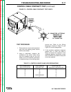
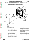
CIRCUIT
BREAKER
PUSH BUTTON
RETAINING
NUTS
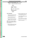
FIGURE F.5 – CIRCUIT BREAKER AND PUSH BUTTON REPLACEMENT.
LN-7 GMA WIRE FEEDER
F-22
CIRCUIT BREAKER REPLACEMENT
(continued)