


Return to Section TOC Return to Section TOC Return to Section TOC Return to Section TOC
Return to Master TOC Return to Master TOC Return to Master TOC Return to Master TOC
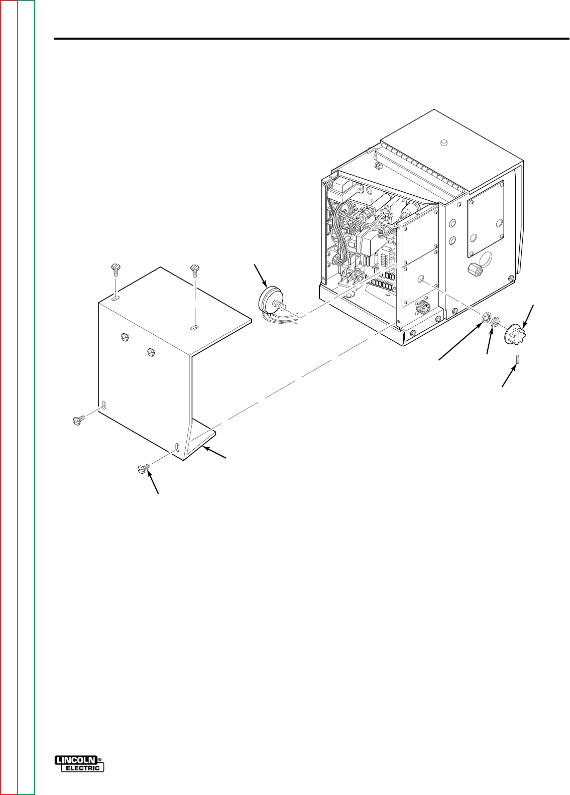
WIRE FEED SPEED POTENTIOMETER REPLACEMENT
(continued)
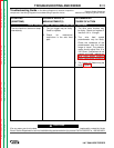
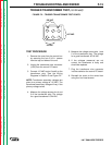
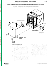
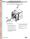
FIGURE F.4 – REMOVING WIRE FEED SPEED POTENTIOMETER.
CONTROL BOX
COVER
5/16 IN.
SCREW
POTENTIOMETER
KNOB
LOCKWASHER
NUT
SETSCREW
TROUBLESHOOTING AND REPAIR F-19
REPAIR PROCEDURE
1. Remove the cover from the control box
by removing the four 5/16 in. screws
from the top and side of the unit. See
Figure F.4.
2. Loosen the setscrew on the
potentiometer knob and remove the
knob from the potentiometer.
3. Remove the nut and lockwasher
holding the potentiometer to the case of
the wire feeder. Remove the
potentiometer through the inside of the
case.
4. Tag the three wires on the potentio-
meter so that they can be reattached in
the same location from which they were
removed. Also refer to the wiring
diagrams in Section G, Electrical
Diagrams. Unsolder the three wires
from the potentiometer.
5. Solder the three wires to the new
potentiometer on the corresponding
terminals from which they were
removed.
LN-7 GMA WIRE FEEDER