


Return to Section TOC Return to Section TOC Return to Section TOC Return to Section TOC
Return to Master TOC Return to Master TOC Return to Master TOC Return to Master TOC
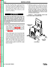
MOUNTING LOCATION
The LN-7 GMA wire feeders can be mounted directly
on top of the power source providing that it is secure
and level. The LN-7 can be mounted to an
undercarriage when portability is required.
A K178-1 swivel platform is available for mounting the
LN-7 GMA to a power source. Refer to the accessories
section for details.
MACHINE GROUNDING
The LN-7 GMA wire feeders are ground to the power
source through the input cable. The power source
grounding terminal must be properly connected to
electrical ground per the power source operating
manual.
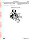
INPUT CABLE CONNECTIONS
Refer to Section C, Accessories, for descriptions of the
various input cable assemblies available for the LN-7
GMA wire feeder.
Turn input power off before connecting the LN-7
GMA wire feeder.
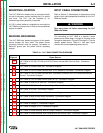
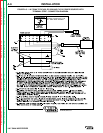
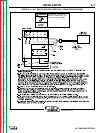
For connecting an LN-7 GMA to a specific Lincoln
power source follow steps 1 through 6, and refer to the
connection diagrams in Figure A.3 through A.17 for the
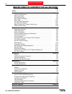
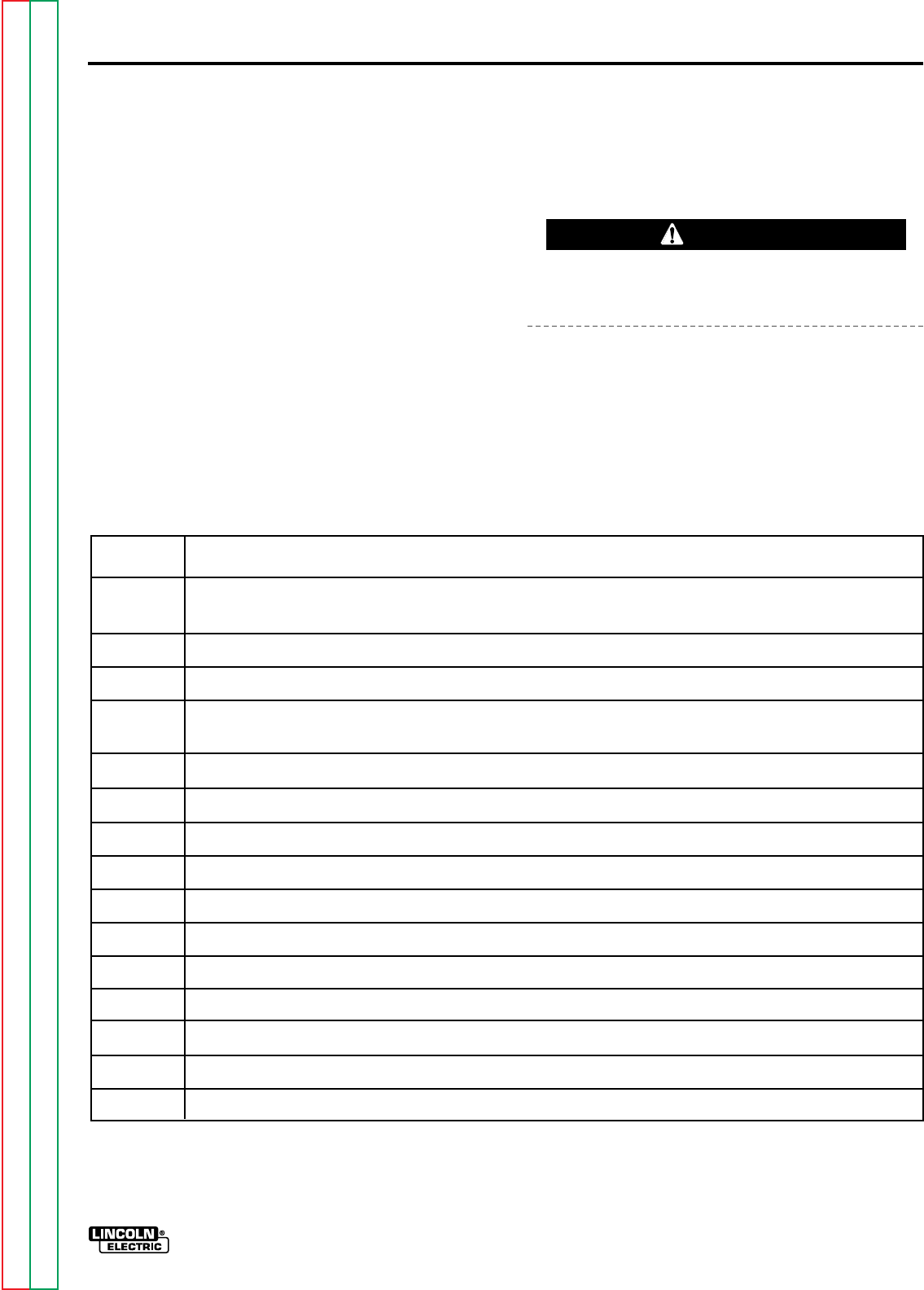
specific power source. Table A.1 lists each figure
number with its corresponding power source.
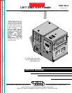
INSTALLATION A-3
LN-7 GMA WIRE FEEDER
WARNING
Figure # Power Source
A.3 LN-7 GMA To DC-400, DC-250 and CV/CVI Power Sources With Terminal Strip - Connection
Diagram
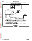
A.4 LN-7 GMA To Pulsed Power 500 - Connection Diagram
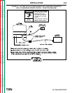
A.5 LN-7 GMA To CV/CVI Power Sources With 14 Pin Amphenol Connector - Connection Diagram
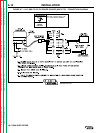
A.6 LN-7 GMA To CV/CVI Power Sources With Twist-Mate Connector and 14 Pin Amphenol/Remote
Control - Connection Diagram
A.7 LN-7 GMA To CV/CVI Power Source (K867/K775) - Connection Diagram
A.8 LN-7 GMA To R3S-250 or R3S-325 - Connection Diagram
A.9 LN-7 GMA To SAM Motor Generator or Engine Welder - Connection Diagram
A.10 LN-7 GMA To DC-600 - Connection Diagram
A.11 LN-7 GMA To R3S-400, 600, or 800 - Connection Diagram
A.12 LN-7 GMA To Most Lincoln Motor Generators - Connection Diagram
A.13 LN-7 GMA To WP250 or G9 PRO - Connection Diagram
A.14 LN-7 GMA To Ranger 9 - Connection Diagram
A.15 LN-7 GMA To Ranger 10-LX - Connection Diagram
A.16 LN-7 GMA To Power Sources With No Output Contactor - Connection Diagram
A.17 LN-7 GMA To Power Sources With Contactor and No Terminal Strip - Connection Diagram
TABLE A.1 - LN-7 GMA CONNECTION DIAGRAMS