


Return to Section TOC Return to Section TOC Return to Section TOC Return to Section TOC
Return to Master TOC Return to Master TOC Return to Master TOC Return to Master TOC
TROUBLESHOOTING AND REPAIR
TEST PROCEDURE
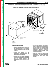
1. Remove the cover from the control box
by removing the four 5/16 in. screws
from the top and sides of the unit.
2. Unplug the transformer wire connector
(J103) from the control PC board.
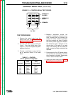
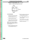
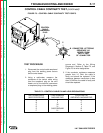
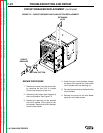
3. Connect 115 VAC to pins 3 and 6 on the
transformer plug. See the Wiring
Diagrams in Section G and Figure F.2.
NOTE: Transformer secondary voltages are
given for a primary voltage of 115 VAC. The
transformer secondary voltage will vary if the
primary voltage varies.
4. Measure the voltage across pins 4 and
5 of the transformer plug. The voltage
for a good transformer is 24 VAC.
5. Measure the voltage across pins 1 and
2 of the transformer plug. The voltage
for a good transformer is 8.8 VAC.
6. If the voltages measured are not
correct, the transformer is faulty and
should be replaced.
7. Plug the transformer wire connector
into the socket on the control PC board.
8. Reinstall the cover on the control box
using four hex head screws.
F-15
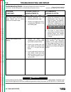
TRIGGER TRANSFORMER TEST
(continued)
FIGURE F.2 – TRIGGER TRANSFORMER TEST POINTS.
1
4
2
5
3
6
24 VAC
8.8 VAC
115 VAC
LN-7 GMA WIRE FEEDER